Transceiver for Wireless Transmission of Field Device Signals

a wireless transmission and field device technology, applied in the field of measurement techniques, can solve the problems of difficult wiring of the devices involved, difficult modification of existing wiring once installed, and complicated wiring of the evaluators and field devices,

Inactive Publication Date: 2007-10-18
VEGA GRIESHABER GMBH & CO
View PDF15 Cites 53 Cited by
  • Summary
  • Abstract
  • Description
  • Claims
  • Application Information

AI Technical Summary

Benefits of technology

[0011]Distinguishing between a first operating state and a second operating state may allow a transceiver to take varying roles in a measured value transmitter without having to use different devices. This means that the wireless transmission of measured values may be realized based on the same hardware platform with only one type of device. The operating state taken by the transceiver may be stipulated. However, the desired operating state may also be detected based on a field device connected to the transceiver, or a connected evaluator. To this end, the transceiver may exhibit a detection device with the ability to detect the type of connected device. Detection may also take place by exchanging a corresponding signal with a code.
[0067]The conduit is mostly a metallic sheathing over a wire connection. A conduit may make it possible to protect a bus against exposure to mechanical influences.

Problems solved by technology

The devices involved are here sometimes difficult to wire, e.g., when obstacles such as river courses must be surmounted.
In addition, existing wiring is difficult to modify once installed.
In like manner, having to expand a measuring device can pose problems, since permanently installed bus systems most often predispose the installation sites of field devices.
Wiring the evaluators and field devices can become a complicated and expensive proposition given complex geographic structures or long distances between field devices, measuring devices, sensors or actuators.
In addition, wiring does not offer any flexibility with respect to modifications.

Method used


Image

  • Transceiver for Wireless Transmission of Field Device Signals
  • Transceiver for Wireless Transmission of Field Device Signals
  • Transceiver for Wireless Transmission of Field Device Signals

Examples


Embodiment Construction

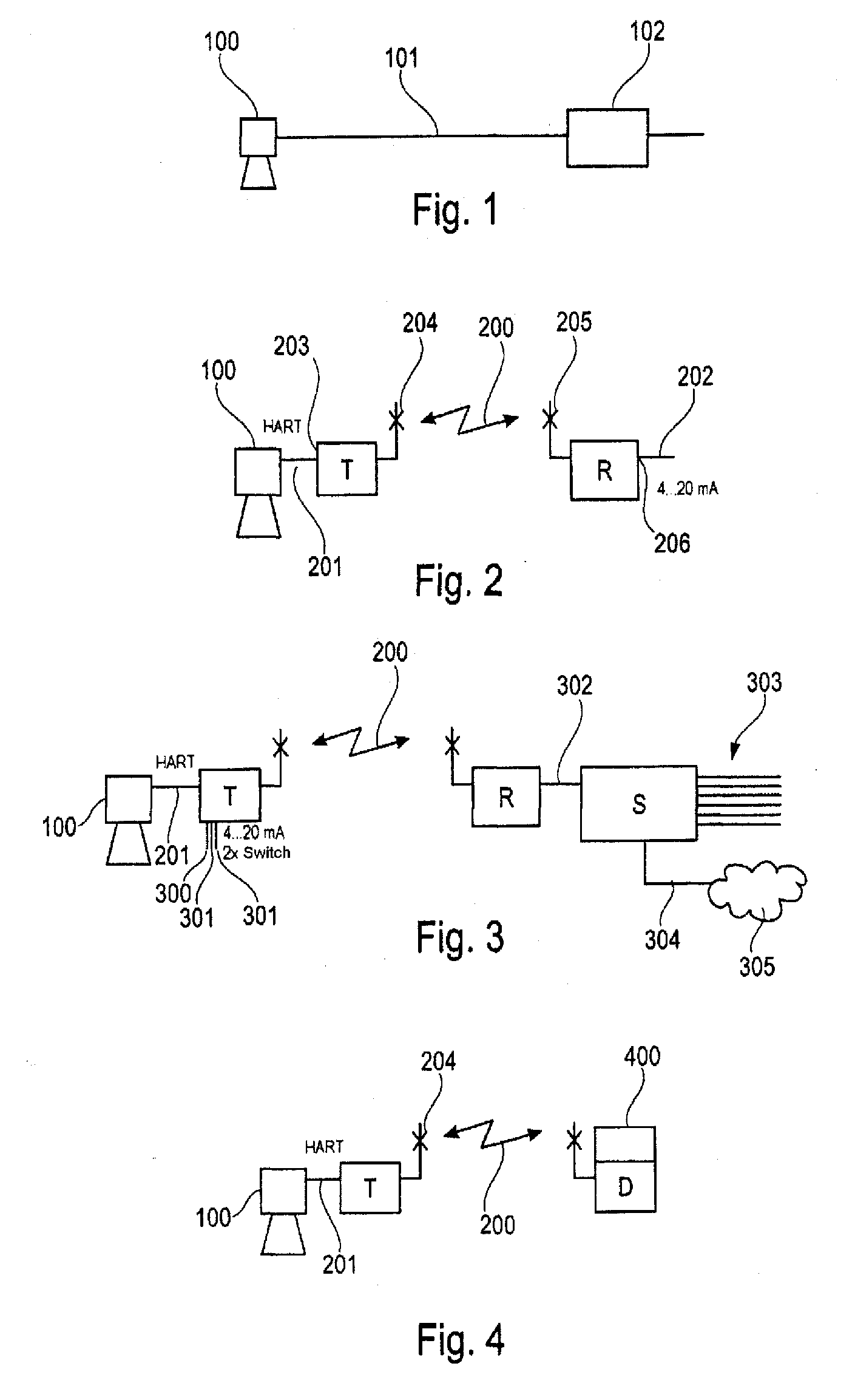
[0100]The representations in the figures are diagrammatic and not to scale. The same reference numbers are used for identical or corresponding elements in the following description of FIG. 1 to FIG. 21.

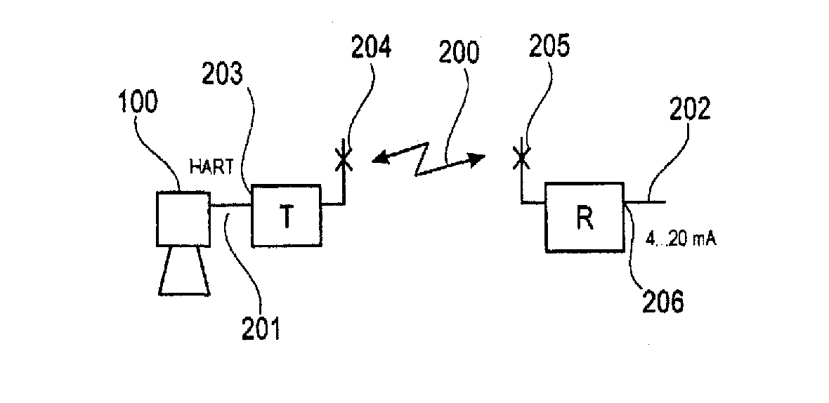
[0101]FIG. 1 shows a hardwired measured value transmission arrangement according to an exemplary embodiment of this invention. The field device 100, measuring device 100, sensor 100 or actuator 100 is here connected with the evaluator 102 or controller 102 via the bus 101, in particular via the field bus 101. The measured values generated by the sensor 100 are relayed over the wire to the evaluator 102. A line can be drawn between analog and digital transmission during transmission between the sensor 100 and evaluator 102 via the bus 101. For example, analog transmission can take place using a 4 . . . 20 mA signal. Digital transmission or digital communication can take place by means of a field bus protocol, e.g., HART® Profibus, Fieldbus Foundation.

[0102]As depicted on FIG. 2, a tran...


PUM


Abstract

A transceiver for wirelessly transmitting process variables with a radio interface and a field device interface is provided. The transceiver has two operating states. The transceiver is designed to receive a field device signal at the field device interface and relay the field device signal via the radio interface in the first operating state. In the second operating state, the transceiver receives a field device signal via the radio interface, and makes the field device signal available at the field device interface.

Description

REFERENCE TO RELATED APPLICATIONS[0001]This application claims the benefit of the filing date of German Patent Application Serial No. 10 2006 017 243.4 filed Apr. 12, 2006 and U.S. Provisional Patent Application Ser. No. 60 / 791,720 filed Apr. 12, 2006, the disclosure of which applications is hereby incorporated herein by reference.FIELD OF THE INVENTION[0002]This invention relates to the field of measurement technique. In particular, this invention relates to a transceiver for the wireless transmission of field device signals, a wireless measured value transmission device, and a method for the wireless transmission of field device signals.TECHNOLOGICAL BACKGROUND OF THE INVENTION[0003]Field device signals are signals provided by a field device, a sensor or a measuring device. Results of measurements, i. e., measured values, are packed or coded in a field device signal. Increasing use is today being made of digitally communicating devices in the area associated with instrumentation t...

Claims


Application Information

Patent Timeline
Patent Type & Authority Applications(United States)
IPC IPC(8): H04B17/00H04B1/38H04M1/00
CPCG05B2219/31121H04L12/4625H04B17/382H04B17/309H04B17/24
Inventor ISENMANN, ANDREASDECK, THOMAS
Owner VEGA GRIESHABER GMBH & CO
Why Eureka
Try Eureka