Prosthetic humeral device and method

a humeral device and humeral tube technology, applied in the field of prosthetic humeral devices, can solve the problems of difficult to control the height of the greater tuberosity, and the contaminated wound with air born matter, so as to reduce the amount of time to perform and reduce the amount of tuberosity fragments. the effect of accurate reduction and secure reduction

Inactive Publication Date: 2007-10-18
STCHUR ROBERT P
View PDF11 Cites 104 Cited by
  • Summary
  • Abstract
  • Description
  • Claims
  • Application Information

AI Technical Summary

Benefits of technology

[0011] The primary object of the present invention is to provide a prosthetic humeral device and method that reduces the amount of tim

Problems solved by technology

As with any medical procedure wherein a patient undergoes surgery, there is always concern relating to contamination of an open wound and the amount of time the open wound is exposed as the longer a wound is open and exposed to the air, the more likely it is that the wound will become contaminated with air born matter.
In addition, as there are a plurality of sutures that are required in order to secure the tuberosities and tendons to the prosthetic, oftentimes the sutures become entangled, thereby making the procedure more complicated and time-consuming.
Furthermore, because the greater tuberosity is sutured to the fin, it is ver

Method used


Image

  • Prosthetic humeral device and method
  • Prosthetic humeral device and method
  • Prosthetic humeral device and method

Examples


first embodiment

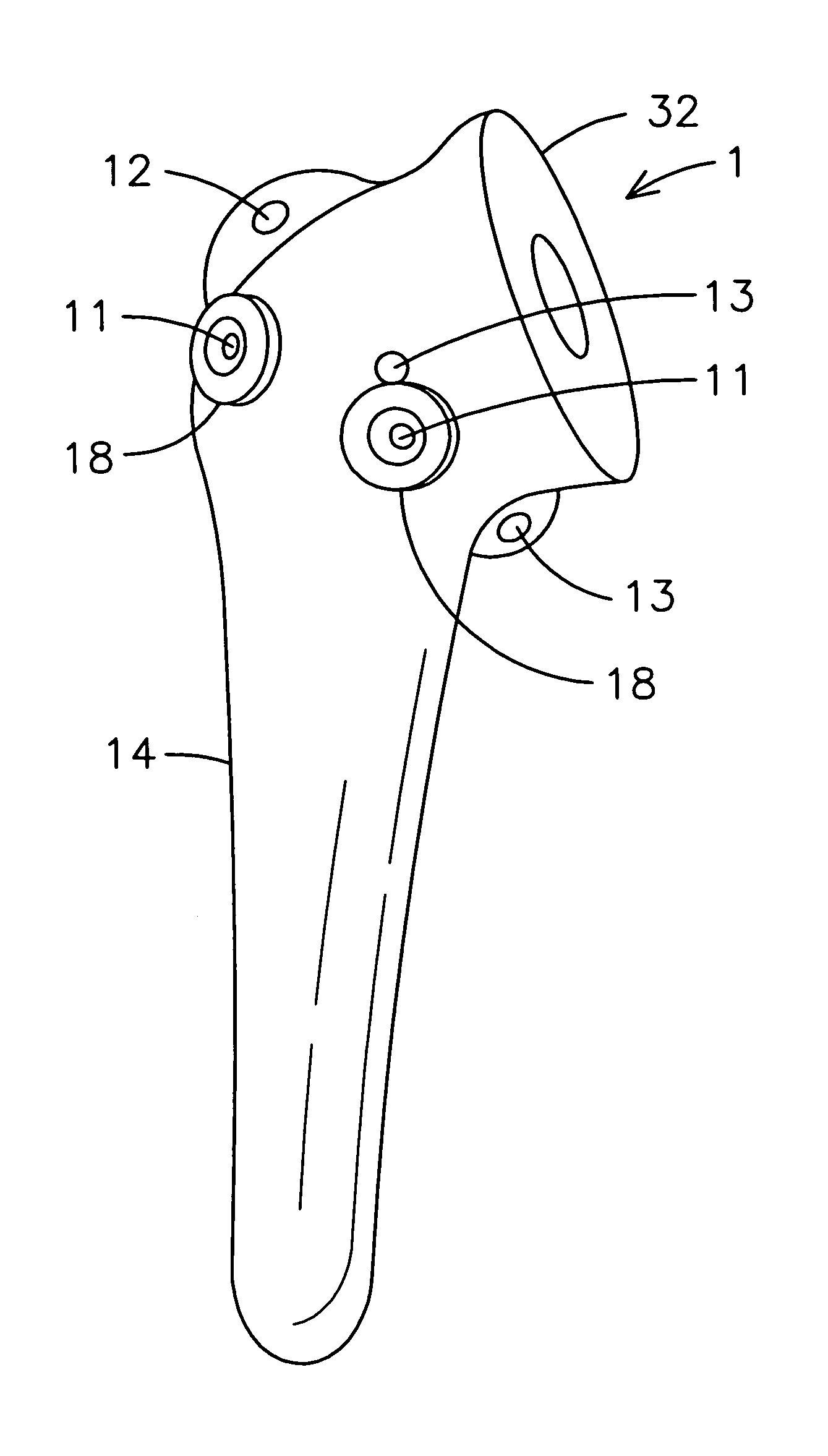
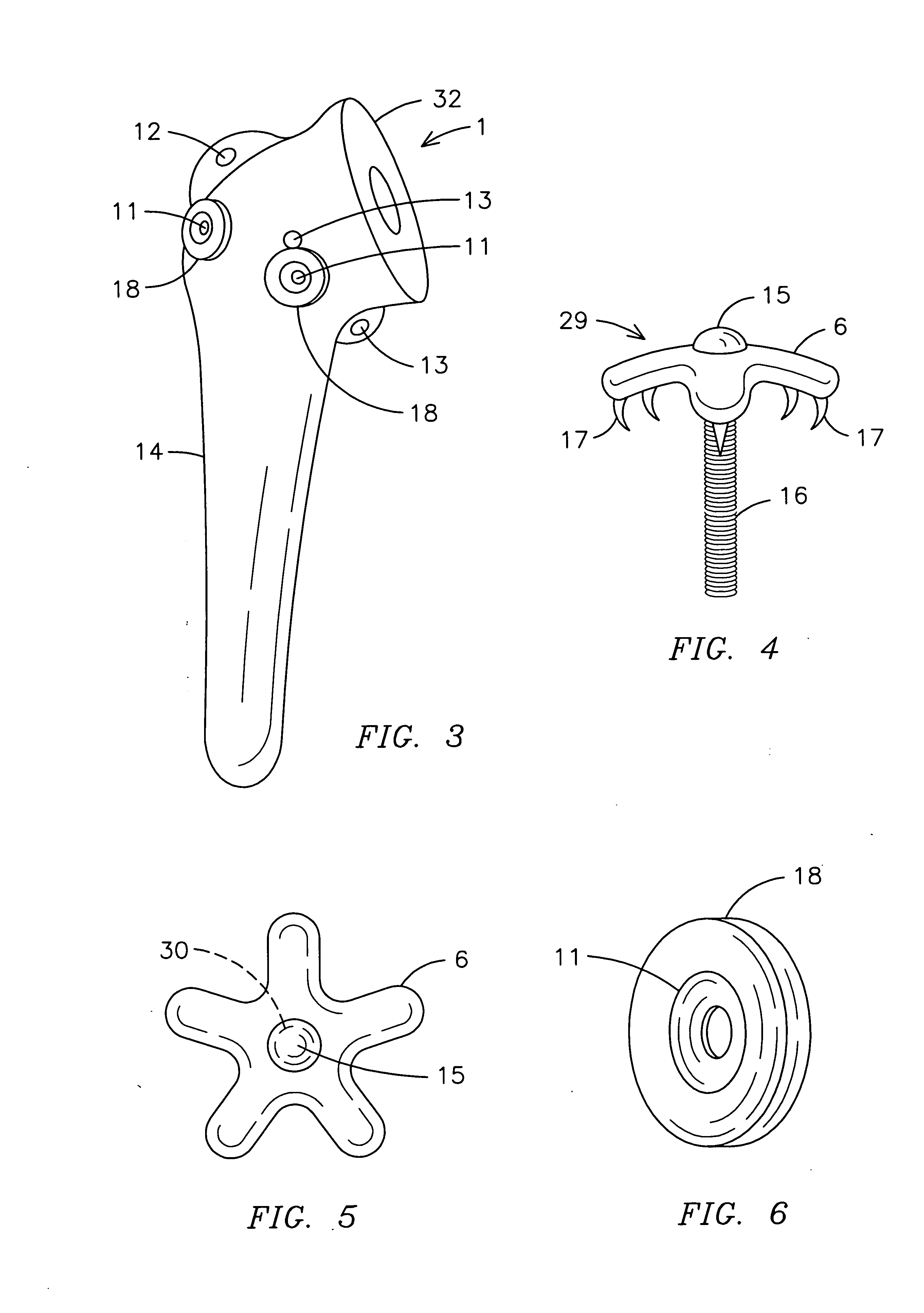
[0036] With reference to FIG. 4, a perspective view of a fastening means of the present invention is shown. The fastening means 29 includes a screw 16 having a screw head 15 that is inserted through a washer 6. Located on an underside of the washer 33 is at least one projection 17 that secures the washer 6 to the humerus 2 and tendons. The washer 6 is preferably convex so as to provide a more conforming securement of the tuberosities to the humerus 2 and prosthetic humeral device 1.

[0037] In FIG. 5, a top view of a first embodiment of a fastening means of the present invention is shown. The washer 6 is preferably star-shaped and has a centrally located hole 30 for the insertion of a screw 16.

[0038]FIG. 6 shows a perspective view of a guiding hole area of the present invention. The guiding hole area 18 includes a guide hole 11 for the insertion of a screw 16. The guide hole 11 narrows so as the diameter of the guide hole 11 becomes smaller to assist in the guidance of the screw 16. ...

second embodiment

[0041] Finally, FIG. 10 shows a perspective view of a fastening means of the present invention. The fastening means 29 may include a star-shaped washer 6 as shown in FIGS. 1, 2, 4 and 5. In the alternative, the washer 6 may be in various other shapes, including having at least two prongs 28. Using the dual-pronged washer 6, a surgeon is able to aim where the fixation point is gained. Similar to the star-shaped washer 6, the dual-pronged washer 6 is convex and includes projections 17 located on the underside of the washer 6.

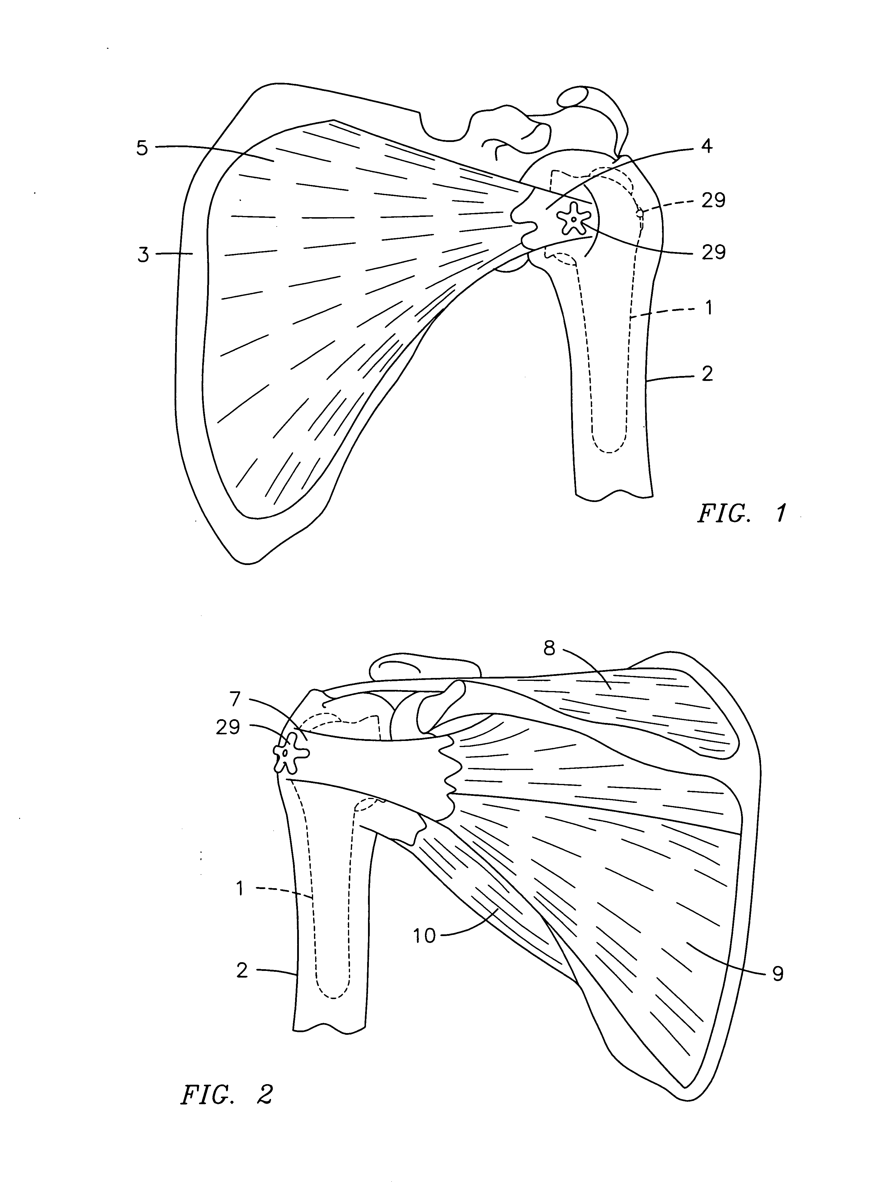
[0042] To use the present invention, a surgeon performs substantially the same steps traditionally used in current hemi-shoulder replacements. That is, a surgeon first makes an incision into the shoulder and mobilize the chunks of bone that have become broken. Then, the surgeon removes the head, greater and lesser tuberosities from the humerus bone. He or she then drills down into the canal of the humerus to create an area for the insertion of a prosthetic humeral...


PUM


Abstract

A prosthetic humeral device (1) having at least two guide holes (11) located at predetermined locations thereon for the acceptance of a fastening means (29), which is preferably a screw (16) and a predeterminedly-shaped washer (6) with at least one projection (17) located on the underside. After inserting the elongated stem (14) of the prosthetic humeral device (1) into the humerus (2), a tuberosity grasping tool (19) is used to grasp a tuberosity (4) and (7). The tuberosity (4) and (7) is then positioned to an appropriate level on the prosthetic humeral device (1), a hole is drilled into the tuberosity (4) and (7), the screw (16) with washer (6) is inserted, the grasping tool (19) is removed and the screw (16) and washer (6) are tightened.

Description

BACKGROUND OF THE INVENTION [0001] This invention relates to prosthetic humeral devices, more particularly, a prosthetic humeral device that employs a threaded fastening means, rather than conventional sutures, to secure the tuberosities in place. A special tool is also provided to assist in the process. [0002] As with any medical procedure wherein a patient undergoes surgery, there is always concern relating to contamination of an open wound and the amount of time the open wound is exposed as the longer a wound is open and exposed to the air, the more likely it is that the wound will become contaminated with air born matter. Thus, time is of the essence when operating on a patient. [0003] Currently, hemi-shoulder replacements, also known as partial shoulder replacements, are surgeries commonly required for proximal humerus fractures or rotator cuff tears wherein a prosthetic humeral is placed within the humerus and attached to the socket via tuberosities and tendons. Conventional h...

Claims


Application Information

Patent Timeline
IPC IPC(8): A61F2/40
CPCA61B17/842A61B17/86A61F2/4059A61F2/4612A61B2017/1778A61F2002/30774A61F2002/30841A61F2002/4062A61F2002/4622A61F2002/30578A61B17/1778
Inventor STCHUR, ROBERT P.
Owner STCHUR ROBERT P
Why Eureka
Try Eureka