Maneuverable Device for Transporting Loads Over a Surface

a technology of transporting devices and surfaces, applied in the direction of nursing beds, transportation and packaging, wheelchair/patient conveyancing, etc., can solve the problems of inability to maintain straight paths, require substantial efforts for controlling and propelling the same, and the longitudinal instability of the bed is difficult to maintain or controllably turn corners, etc., to prevent potential injuries or stress to the user, reduce the motive effort of the user

Inactive Publication Date: 2007-10-25
SAVION INDS 1987
View PDF12 Cites 44 Cited by
  • Summary
  • Abstract
  • Description
  • Claims
  • Application Information

AI Technical Summary

Benefits of technology

[0020] Thus, according to the invention, when the device is in the powered mode, the device provides its own motive force, for level or inclined paths, and the user, such as a hospital orderly or airport attendant for example, merely has to steer the platform. ...

Problems solved by technology

However, in this mode the bed is longitudinally unstable, and is difficult to maintain in straight path or to controllably turn corners during long range transportation, particularly when the bed is loaded with a patient.
Nevertheless, such beds still require substantial efforts for controlling and propelling the same, sometimes necessitating more than one orderly for this purpose if collisions are to be avoided.
Particularly when only one orderly is used for transporting a p...

Method used


Image

  • Maneuverable Device for Transporting Loads Over a Surface
  • Maneuverable Device for Transporting Loads Over a Surface
  • Maneuverable Device for Transporting Loads Over a Surface

Examples


first embodiment

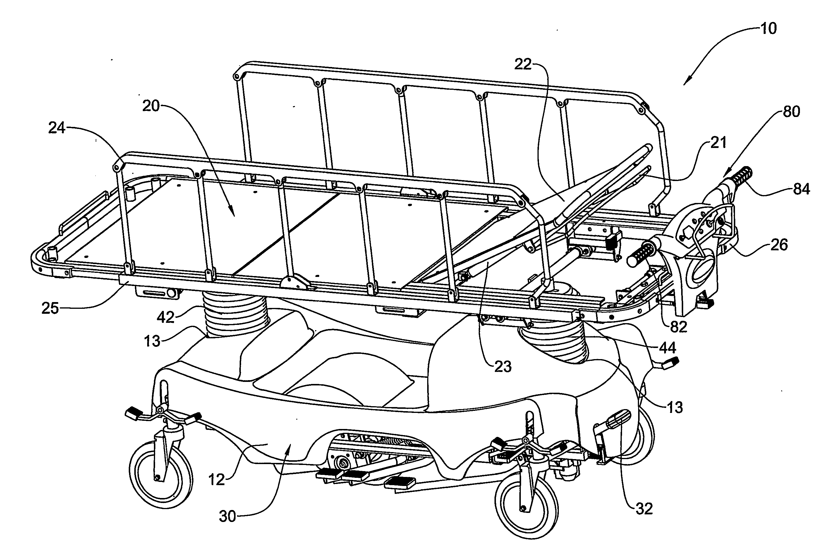
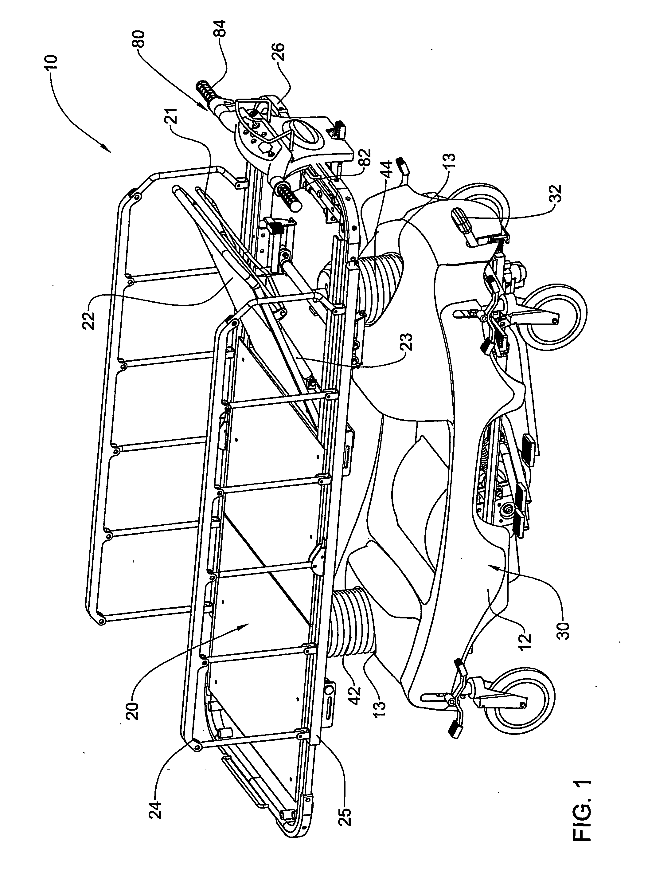
[0041] the invention, illustrated in FIGS. 1 to 4, comprises a maneuverable bed, generally designated with the numeral 10, having a platform 20 mounted onto a wheeled base 30.

[0042] The platform 20 is generally adapted for accommodating a patient, which may be an adult or a child, for example, in the lying position. In other applications the bed may be adapted for accommodating an animal, for example in a veterinary's clinic. In this embodiment, the platform comprises one or more tilting portions, such as portion 22, that is pivotably mounted with respect to a remainder of said platform. Portion 22 may be selectively tilted with respect to the rest of the platform 20, enabling the patient to sit up on the bed, for example. For this purpose, the portion 22 comprises an actuation handle 21, and supporting extendible jack 23. Furthermore, the platform 20 is mounted to the base 30 via longitudinally spaced columns 42, 44, which are adjustable in height, separately or together, and thus ...

second embodiment

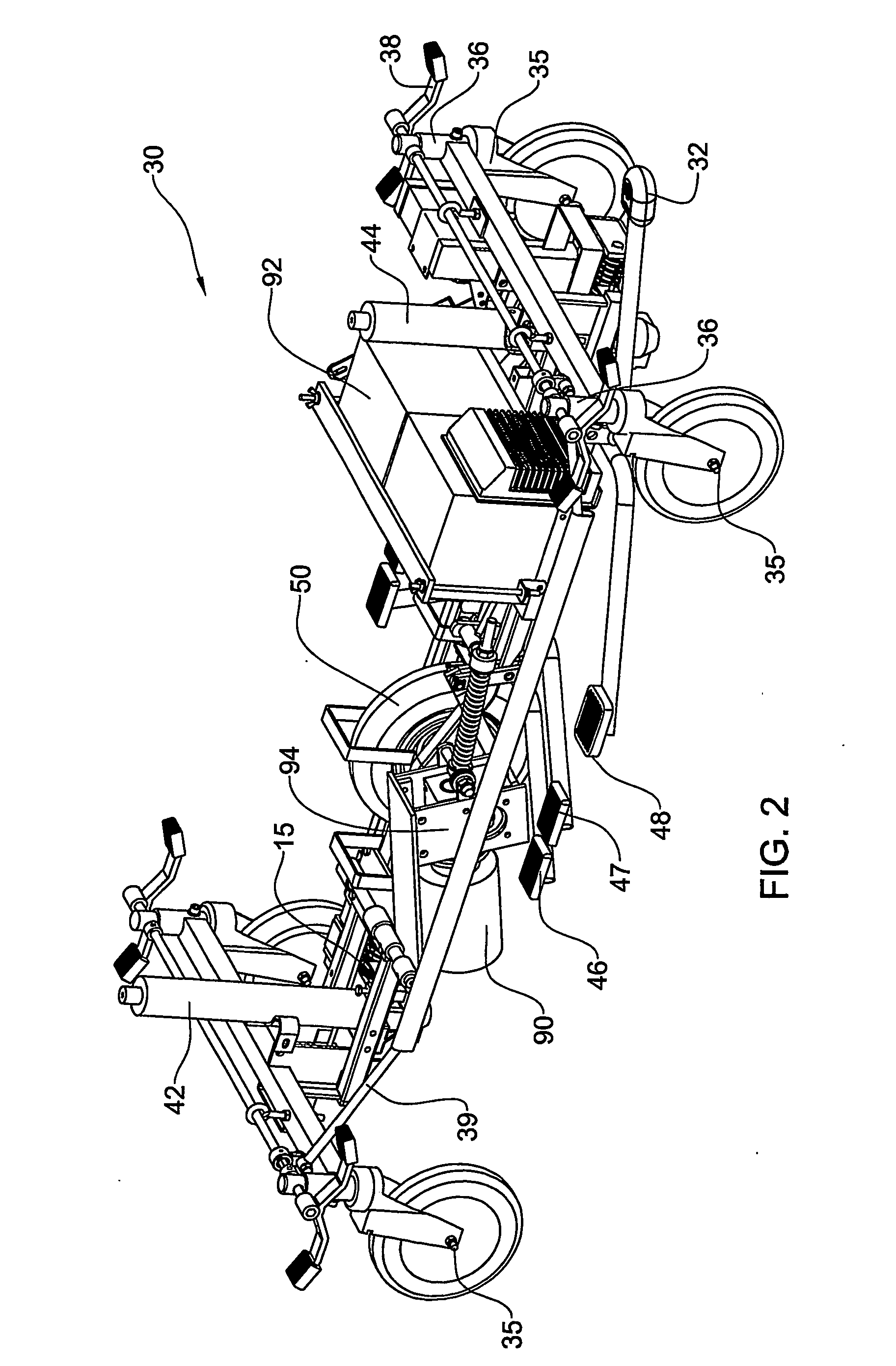
[0068] In the second embodiment, the castors 35 are each capable of assuming any one of the three modes: neutral, steer and brake modes. Similarly to prior art arrangements, in the neutral mode each castor 35 can freely swivel with respect to the castor housings 36, and in the brake mode the castor wheel is prevented from turning in the castor. However, in the steering mode, each castor 35 is locked in position with respect to a castor housing 36. Each castor housing 36 is pivotably mounted with respect to the base 30, and can assume any angular position about an axis substantially parallel to the swivel axis of the castor.

[0069] A steering mechanism 60 is provided, which in this embodiment comprises a link arrangement linking the castor housings 36 to one another, such that on the one hand, when the castors 35 are in steering mode, the rotational axes A′ of the wheels of the castors 35 are parallel one to the other, and also parallel to the auxiliary wheel 50, enabling the bed 10 t...


PUM


Abstract

A maneuverable device for transporting a load over a surface, which finds particular application in a hospital bed for the transportation of patients and in a wheelchair for transporting patients or passengers in an air terminal, for example. The device has a platform for supporting a load to be transported mounted on a base comprising a plurality of castors. One or more one auxiliary wheels are mounted for rotation about at least one fixed axis with respect to said base, and a power unit configured for providing motive power to the auxiliary wheels is provided. A driving unit is provided for steering the device, the driving unit operating independently of the auxiliary wheels.

Description

FIELD OF THE INVENTION [0001] This invention relates to a transportation device. More particularly the present invention relates to maneuverable devices that can be selectively moved manually or under power, and especially adapted for use as a patient trolley or hospital bed. BACKGROUND OF THE INVENTION [0002] Wheeled hospital beds are a major form of transportation for patients in a hospital. Such beds are used for the long range transportation of patients from one location of a hospital to a different location, for example, and also for short-range maneuvering of the bed into a parking position within a room. Accordingly, the beds are typically designed with castors in a rectangular array approximately underlying a patient-supporting platform to enable the bed to be maneuvered in any direction. The castors can generally be fixed in one of three modes: neutral, steer and brake modes. In the neutral mode, each castor is free to swivel about its pivot, and allows the bed to be maneuv...

Claims


Application Information

Patent Timeline
IPC IPC(8): A61G1/02A61G1/048A61G5/04A61G7/002A61G7/012A61G7/015A61G7/018A61G7/05A61G7/08B60B33/00
CPCA61G7/0507A61G1/0281A61G2007/0509A61G2007/0528B60B33/0039B60B33/0049B60B33/0057B60B33/0063B60B33/0068B60B33/0073B60B33/066A61G7/012A61G7/015A61G7/018A61G7/05A61G1/0237A61G1/0225A61G1/0268A61G1/0275A61G1/0287A61G7/08A61G1/0243A61G7/0509A61G7/0528A61G2203/80
Inventor ZIMBALISTA, DOVZIMBALISTA, RAN
Owner SAVION INDS 1987
Why Eureka
Try Eureka