Lubrication structure of engine

a technology of lubricating structure and engine, which is applied in the direction of auxilaries, machines/engines, mechanical equipment, etc., can solve the problems of increasing the height of the engine, and reducing the lubricating oil supply from the crank chamber. , to achieve the effect of reducing the agitation loss of lubricating oil from the crankshaft and other things

Active Publication Date: 2007-10-25
HONDA MOTOR CO LTD
View PDF2 Cites 5 Cited by
  • Summary
  • Abstract
  • Description
  • Claims
  • Application Information

AI Technical Summary

Benefits of technology

[0011]The flow of lubricating oil that flows out of the crank chamber is smoothed and the lubricating oil hardly stays in a space before and after the reed valve (in the first oil reservoir and the second oil reservoir) when the lubrication structure of the engine according to the invention is configured as described above. Therefore, the lubricating oil in the crank chamber is promptly exhausted and the agitat

Problems solved by technology

Therefore, the lubricating oil is apt to stay in a space before and after the reed valve and an efficiency problem occurs, wherein the lubricating oil is not exhausted from the crank chamber sufficiently.
On the other hand, a larger space is required for the lubricating oil exhausted from the reed valve on the downstream sid

Method used


Image

  • Lubrication structure of engine
  • Lubrication structure of engine
  • Lubrication structure of engine

Examples


Embodiment Construction

[0020]The present invention will now be described in detail with reference to the accompanying drawings, wherein the same reference numerals will be used to identify the same or similar elements throughout the several views.

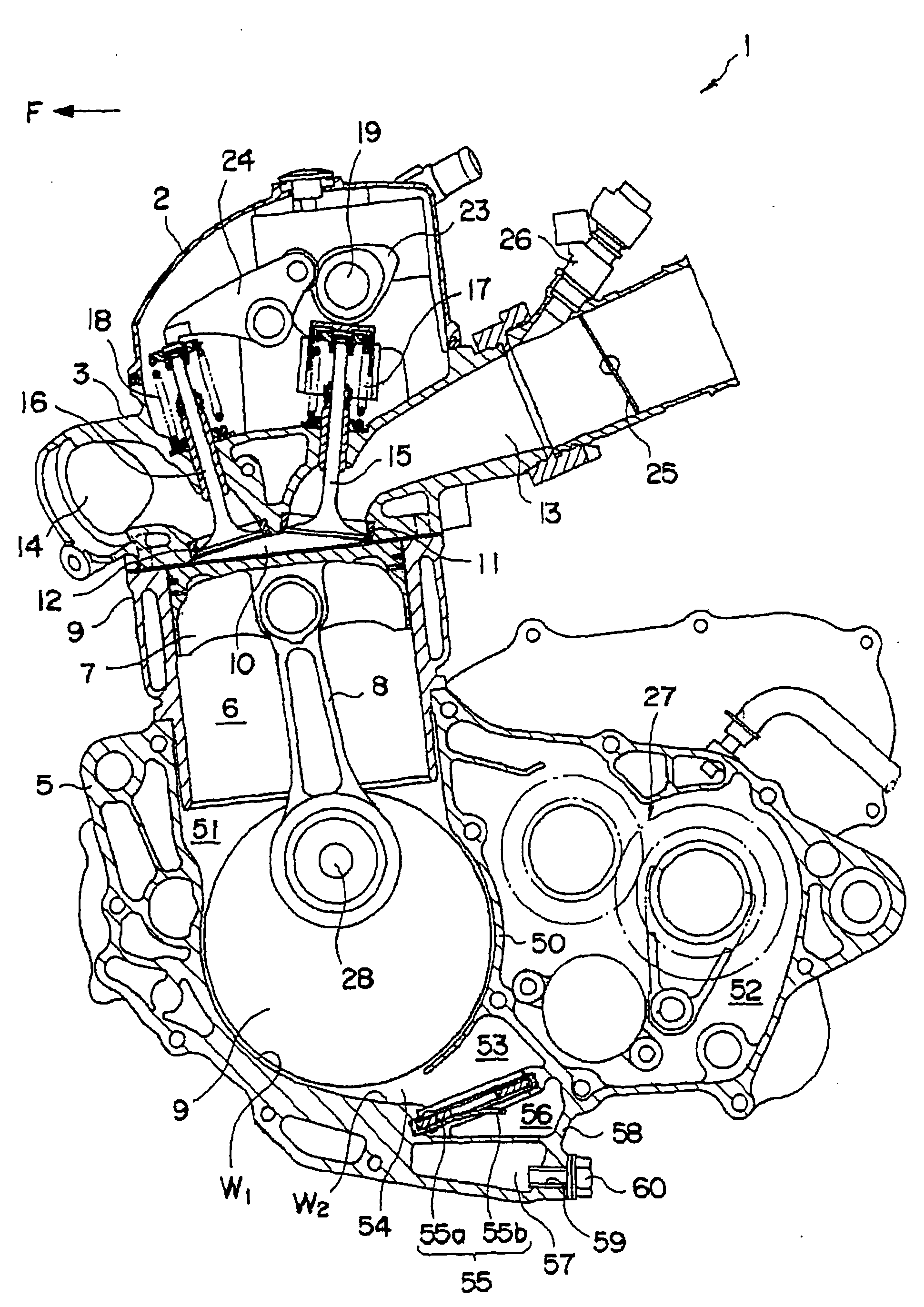
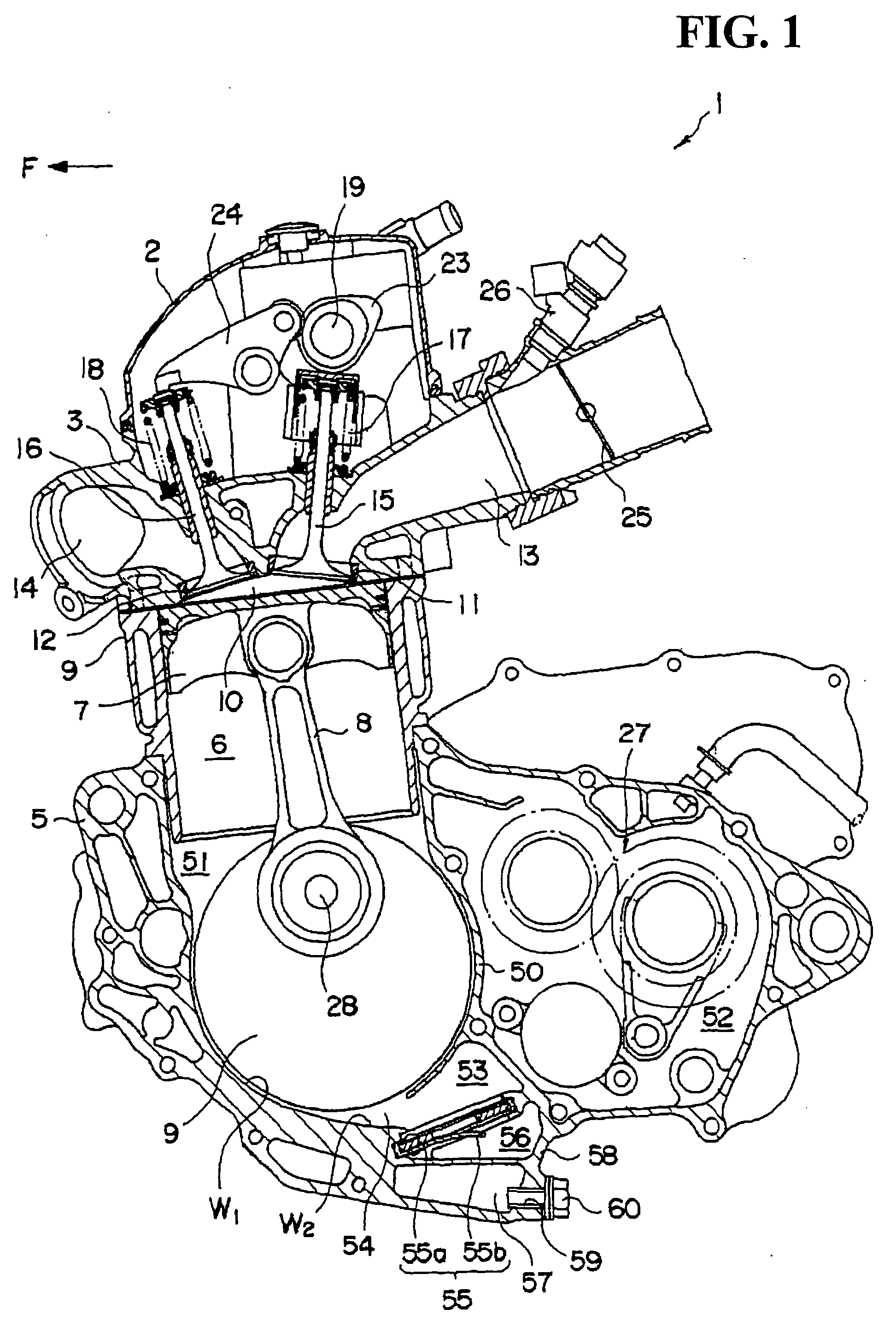
[0021]Referring to the drawings, a preferred embodiment of the invention will be described below. First, referring to FIG. 1, an engine 1 to which lubrication structure according to an embodiment of the present invention is applied will be described. The engine 1 is used for a motorcycle, particularly for a motorcycle for off-road driving sports. In the following description, an arrow F shown in FIG. 1 points to the front of the motorcycle.

[0022]The engine 1 includes a cylinder head cover 2, a cylinder head 3, a cylinder block 4 and a crankcase 5. A cylinder chamber 6 that extends vertically and cylindrically is formed in the cylinder block 4. A piston 7 is arranged in the cylinder chamber 6 so that the piston can be vertically slid and is connected to a cranksha...


PUM


Abstract

The lubrication structure of an engine is provided with a crankcase having a crank chamber that houses a crankshaft. A first oil reservoir is in communication with the crank chamber and is formed adjacent a bottom of the crank chamber. A second oil reservoir is in communication with the first oil reservoir and is formed adjacent the side of and on the bottom of the first oil reservoir. A reed valve extends diagonally from the bottom of the first oil reservoir toward the top of the second oil reservoir in an opening where the first oil reservoir and the second oil reservoir communicate with the crankcase. The reed valve includes a valve element that opens and closes according to the variation of pressure in the crank chamber. The valve element of the reed valve is arranged on the side of the second oil reservoir.

Description

CROSS-REFERENCE TO RELATED APPLICATIONS[0001]This nonprovisional application claims priority under 35 U.S.C. §119(a) on Patent Application No. 2006-120691, filed in Japan on Apr. 25, 2006, the entirety of which is incorporated herein by reference.BACKGROUND OF THE INVENTION[0002]1. Field of the Invention[0003]The present invention relates to a lubrication structure of an engine that is suitable for a motorcycle, particularly a motorcycle that is used for off-road driving sports.[0004]2. Background of the Invention[0005]As an agitation loss is caused due to a crankshaft and other things when a motorcycle is run in a state in which lubricating oil accumulates in a crankcase of an engine, a reed valve is provided between a crank chamber and an oil pan to prevent the lubricating oil exhausted into the oil pan from the crank chamber from flowing in a reverse direction into the crank chamber. The reed valve is arranged vertically, that is, so that a valve element is open in a lateral dire...

Claims


Application Information

Patent Timeline
IPC IPC(8): F01M1/02F02B77/00
CPCF01M1/04F02B61/02F01M2001/126
Inventor TAKEMOTO, KAZUHISAONOZATO, TOMIO
Owner HONDA MOTOR CO LTD
Why Eureka
Try Eureka