Compressor for fuel cell

a fuel cell and compression chamber technology, applied in the direction of liquid fuel engines, sliding contact bearings, machines/engines, etc., to achieve the effect of excellent durability

Inactive Publication Date: 2007-10-25
JTEKT CORP
View PDF8 Cites 23 Cited by
  • Summary
  • Abstract
  • Description
  • Claims
  • Application Information

AI Technical Summary

Benefits of technology

[0006] In view of the above circumstances, it is an object of this invention to provide a compressor for a fuel cell in which its compact design is achieved by using a centrifugal compressor, and a variation in axial force due to rotation of an impeller (which is a problem to be solved for achieving the compact design) is absorbed, thereby providing the compressor which is advantageous for use in high-speed rotation, and besides has excellent durability.

Problems solved by technology

However, in the centrifugal compressor, a variation in axial force acting on the impeller is large, and therefore it is necessary to secure the durability of an associated bearing device.

Method used


Image

  • Compressor for fuel cell
  • Compressor for fuel cell
  • Compressor for fuel cell

Examples


first embodiment

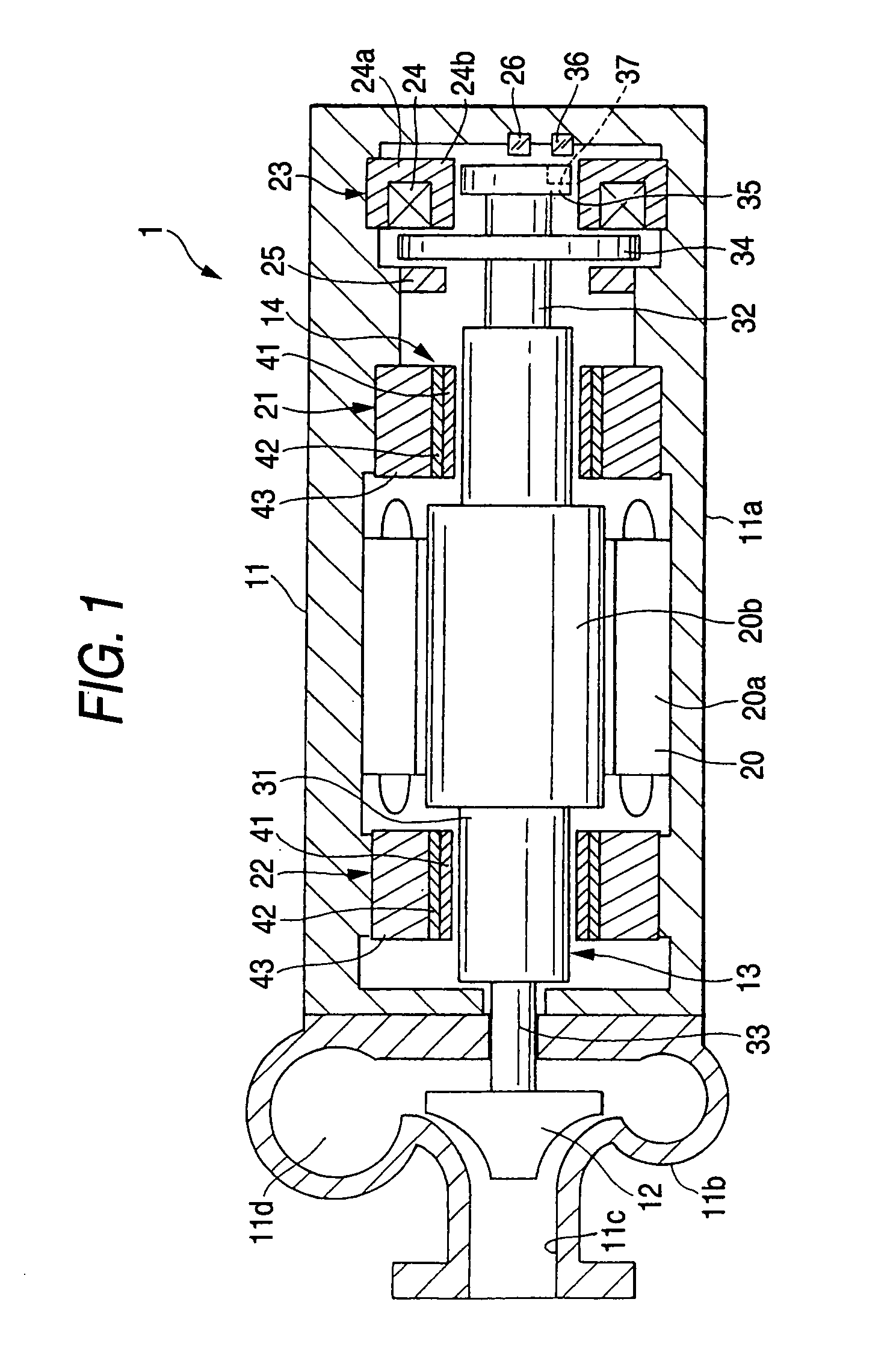
[0035]FIG. 1 schematically shows the construction of a fuel cell compressor of the invention. The compressor 1 for a fuel cell is a non-displacement type centrifugal compressor, and comprises a sealed casing 11 of a substantially cylindrical shape disposed on a horizontal axis extending in the front-rear direction, a rotation shaft (horizontal shaft) 13 having an impeller 12 formed at a rear end thereof and rotatable within the casing 11, a bearing device 14 supporting the rotation shaft 13, and a control device 61 for controlling the rotation shaft 13 and the bearing device 14.

[0036] The casing 11 includes a front-side rotation shaft support portion 11a, and a rear-side gas passage portion 11b within which the impeller 12 is disposed.

[0037] The rotation shaft 13 is in the form of a stepped shaft, and is disposed in a space within the rotation shaft support portion 11a.

[0038] A built-in motor 20 for rotating the rotation shaft 13 at high speed, a pair of front and rear radial foil...

second embodiment

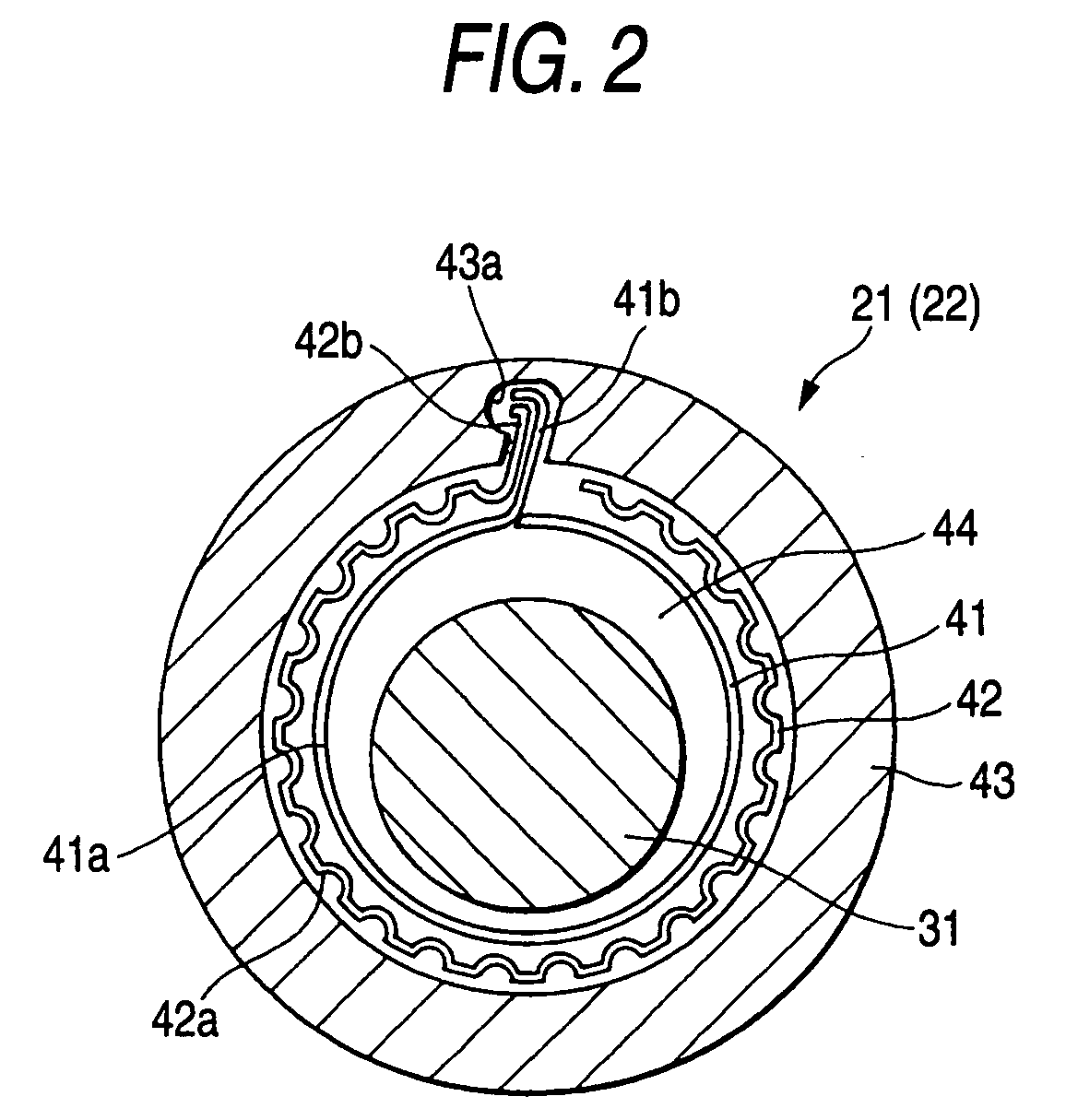
[0070] In FIG. 7, the front radial foil bearing 51 is formed into an axial electromagnet-incorporating bearing, and with this construction the permanent magnet 57 provided at the rear portion in FIG. 6 is omitted, and a flange portion 58 opposed to the axial electromagnet 56 is additionally formed at a front end of a rotation shaft 13. The front radial foil bearing 51 having the axial electromagnet 56 formed integrally therewith is similar to the front radial foil bearing of the second embodiment, but is reversed in the front-rear direction. This front radial foil bearing 51 comprises a flexible top foil 41 having a bearing surface radially opposed to the rotation shaft 13, a bump foil 42 supporting the top foil 41, an outer ring 53 holding the top foil 41 and the bump foil 42 between it and the rotation shaft 13, and an electromagnet coil 56a which is fitted in an annular recess 54 formed in a front end surface of the outer ring 53, and is opposed to the flange portion 58 of the ro...


PUM


Abstract

A bearing device supporting a rotation shaft of a fuel cell compressor includes a pair of radial foil bearings and mounted in concentric relation to the rotation shaft and supporting the rotation shaft in a radial direction, and an axial magnetic bearing opposed to the rotation shaft in an axial direction and supporting the rotation shaft in the axial direction. A control device includes bearing life diagnostic unit for accumulating times during which a rotational speed of the rotation shaft has been below a predetermined value, so as to obtain a cumulative contact time, thereby judging a bearing lifetime.

Description

BACKGROUND OF THE INVENTION [0001] This invention relates to a compressor for a fuel cell which is provided at an oxygen supply side of a fuel cell apparatus for producing energy from hydrogen and oxygen, and supplies compressed air to a fuel cell, and more particularly to a compressor for a fuel cell suitable for being mounted on a fuel cell vehicle. [0002] Prototypes of fuel cell vehicles, running using a fuel cell mounted thereon, have already been manufactured, and there has been proposed in JP-A-2002-70762 Publication a scroll compressor suited for use as a compressor for supplying compressed air to a fuel cell of a fuel cell vehicle. [0003] As a compressor other than the scroll type, there is known a centrifugal compressor (also called a turbine compressor) in which a rotation shaft having an impeller formed at one end thereof is rotated within a casing, and the air is compressed in a space within a gas passage portion of the casing by rotation of the impeller (JP-A-7-91760 Pu...

Claims


Application Information

Patent Timeline
Patent Type & Authority Applications(United States)
IPC IPC(8): F02B53/00
CPCF04D25/0606F04D29/057F04D29/058F16C17/024F16C2360/44F16C32/0402F16C32/0476F16C2360/42F16C17/24F04D29/051
Inventor TANIGUCHI, MANABUUEYAMA, HIROCHIKAMIYAGAWA, YASUTAKA
Owner JTEKT CORP
Why Eureka
Try Eureka