Cartridge-filter cleaning machine

a cartridge filter and cleaning machine technology, applied in the direction of cleaning processes and apparatus, cleaning using liquids, separation processes, etc., can solve the problems of maintenance personnel, filtration pump working harder and harder, present cleaning methods are questionable at best, etc., to reduce the effectiveness and efficiency of the filter, the effect of not straining the system

Inactive Publication Date: 2007-10-25
CRAWFORD RANDAL W +1
View PDF12 Cites 18 Cited by
  • Summary
  • Abstract
  • Description
  • Claims
  • Application Information

AI Technical Summary

Benefits of technology

[0006] It is an object of the present invention to provide a machine for cleaning cartridge filters efficiently and effectively, in a controlled manner.
[0007] Another object of the present invention is to restore a cartridge filter to its best possible condition so that its continued use with a pool water filtration system does not strain the system or diminish its effectiveness and efficiency.
[0008] Yet another object of the present invention is to increase the life expectancy of cartridge filters so they don't have to be replaced as often.
[0009] A further object of the present invention is to increase the life expectancy of pool water filtration systems by providing a cost-effective machine that encourages pool owners to have their cartridges filters cleaned on a regular basis.

Problems solved by technology

As the debris accumulates, the filtration pump must work harder and harder to pull water through the cartridge filter.
Present cleaning methods are questionable at best.
Typically, swimming pool maintenance personnel and swimming pool owners try unsuccessfully to completely and thoroughly clean their filter cartridges.
However, the proposed devices are messy and not particularly effective.
Further, a garden hose cannot be used to effectively clean the inside of a cartridge filter.
When a cartridge filter cannot be satisfactorily cleaned, a pool owner will prematurely replace his pool's dirty cartridge filters with new ones, at great cost, and will discard the used cartridge filters in a landfill.

Method used


Image

  • Cartridge-filter cleaning machine
  • Cartridge-filter cleaning machine
  • Cartridge-filter cleaning machine

Examples


Embodiment Construction

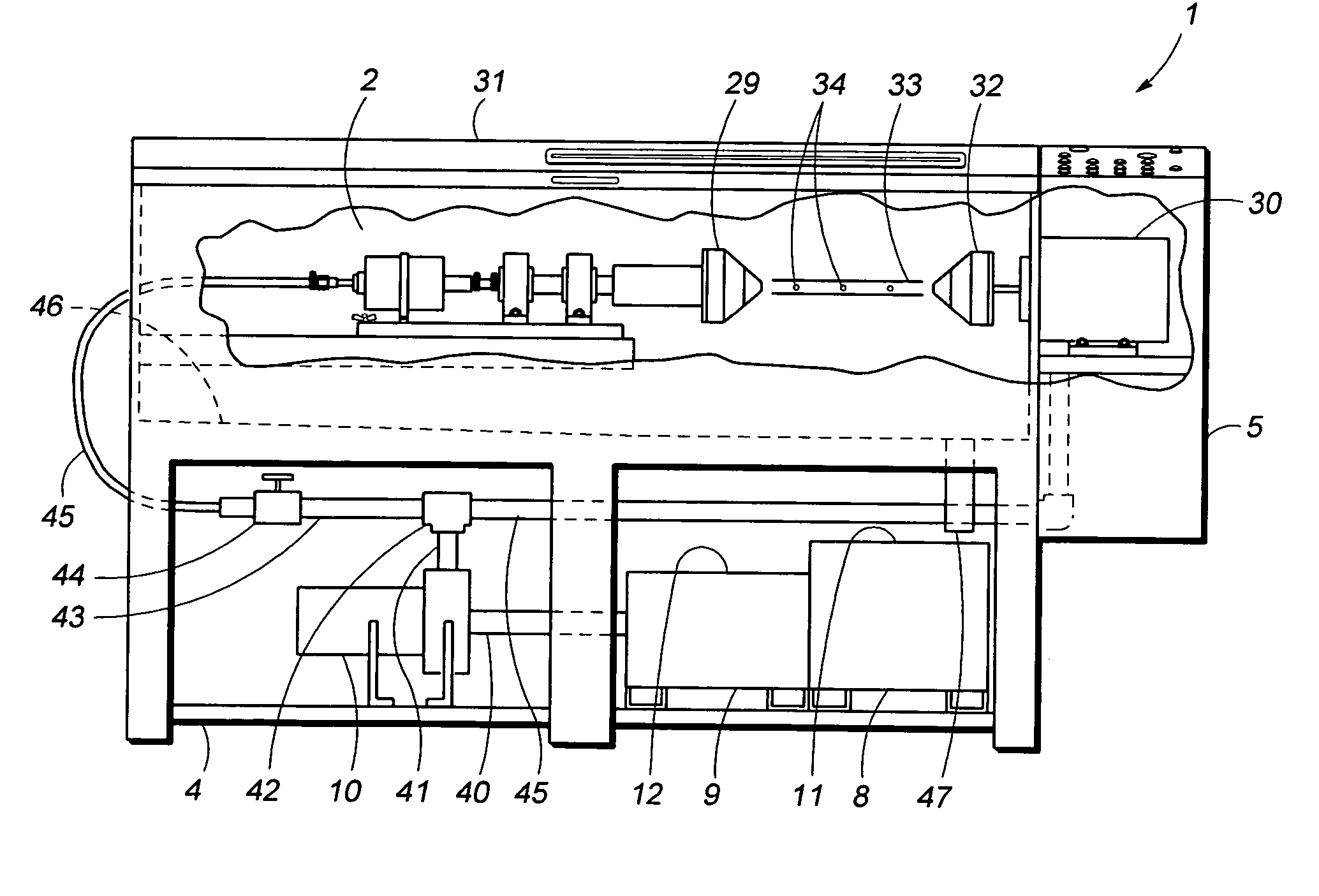
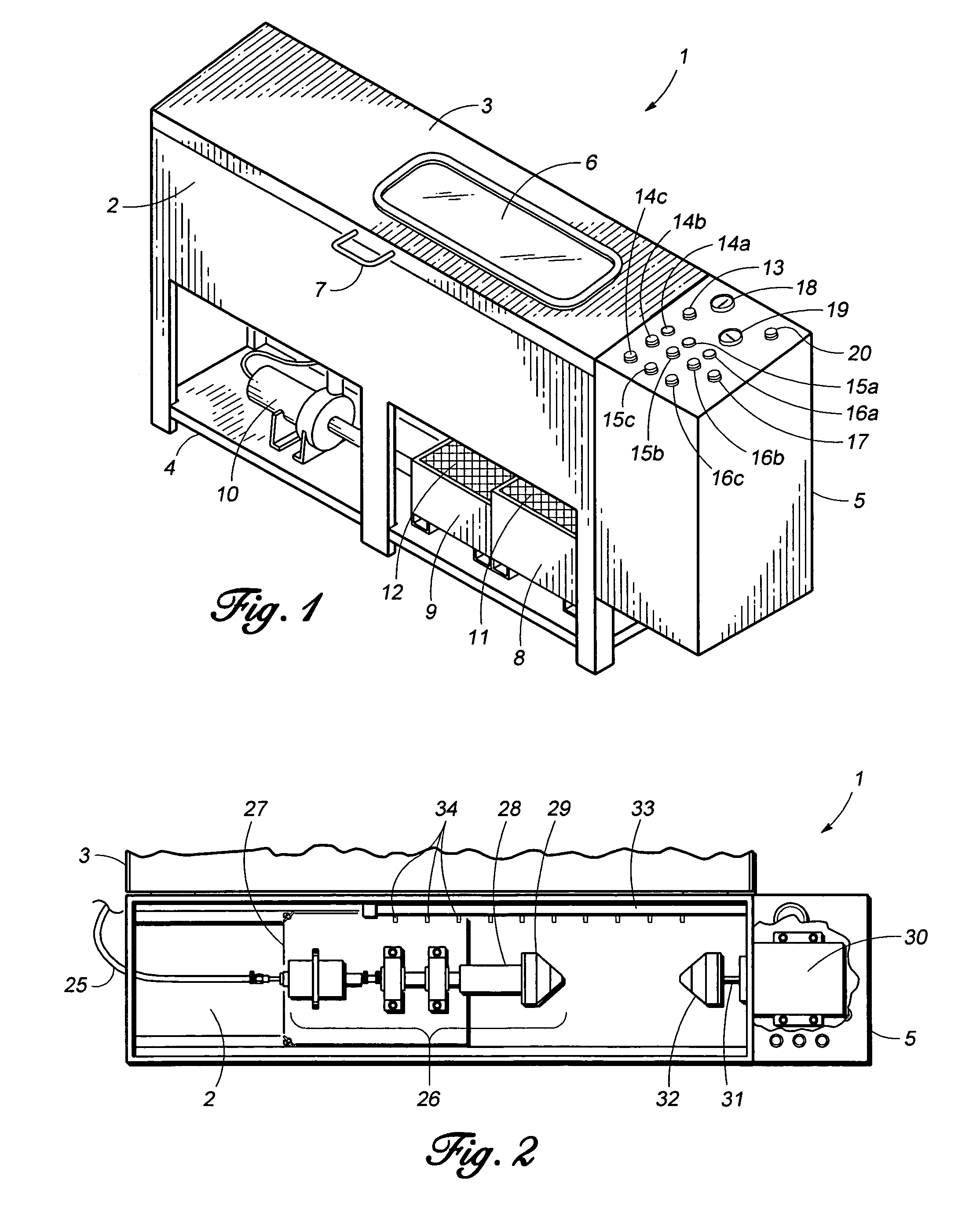
[0017] As shown in FIG. 1, the box-shaped cartridge-filter cleaning machine 1 of the present invention has a cleaning chamber 2, a lid 3, a support shelf 4, and a control panel console 5. Power and water are supplied to the cartridge-filter cleaning machine 1 by conventional means. The lid 3 has a wire safety glass window 6, which allows the user to view the cycles of the cleaning process. The handle 7 is used to open and close the lid 3. The support shelf 4 supports a primary reservoir 8, a secondary reservoir 9, and a water pump 10. Each reservoir 8, 9 is covered with mesh screen 11, 12, which traps dirt and debris from the cleaning operation. Atop the control panel console 5 is an array of switches and gauges. Main power supply switch 13 controls power to the cartridge-filter cleaning machine 1. Power supplied to the cartridge-filter cleaning machine 1 can be generated by electricity or by use of a combustible fuel, such as gasoline, propane, etc. Water pump activation button 14a...


PUM

PropertyMeasurementUnit
temperatureaaaaaaaaaa
centrifugal forceaaaaaaaaaa
lengthaaaaaaaaaa

Abstract

A machine for cleaning cartridge filters used in pool filtration systems. The machine has a cleaning chamber which holds an adjustable tail stock assembly with a first cone and a second cone mounted onto a power-driven motor. The cones are pulled apart to accommodate a dirty cartridge filter. One end of the cartridge filter is placed against the second cone, and the first cone, which can be spring-loaded, is pressed against the other end of the cartridge filter. The cartridge filter is then locked in place. The power-driven motor spins the second cone, while heated water is injected into and through the hollow shafts of the tail stock assembly and the first cone, and into the perforated tube of the cartridge filter, where centrifugal force causes the water to leave the tube of the cartridge filter, carrying away dirt deposits on the surface of the cartridge. A row of spray nozzles can be used to rinse the cartridge filter. The used water is filtered, reheated, and recirculated back into the cleaning chamber.

Description

FIELD OF THE INVENTION [0001] The present invention relates to a machine for effectively cleaning a cartridge filter used to filter water in swimming pools. BACKGROUND OF THE INVENTION [0002] Cartridge filters are one type of filter used with swimming pool filtration systems. A cartridge filter is typically cylindrical in shape, with longitudinal pleats made from porous filtering material. The pleats are mounted onto a perforated tube. The dirt and debris removed from the pool by the filtration system collects on the surface of the pleats when water is drawn from the pool through the filtering material of the cartridge filter and into the tube. The filtered water then exits from the top of the cartridge filter and is returned to the pool. As the debris accumulates, the filtration pump must work harder and harder to pull water through the cartridge filter. At some point, the pool owner must try to clean the cartridge filter so that the filtration system can work more efficiently. [00...

Claims


Application Information

Patent Timeline
Patent Type & Authority Applications(United States)
IPC IPC(8): B08B3/04B08B3/00B08B3/12B08B9/00
CPCB01D41/04B08B3/02B08B9/0321B08B9/023B08B3/10
Inventor CRAWFORD, RANDAL W.SHAHAN, GREGORY ALLEN
Owner CRAWFORD RANDAL W
Why Eureka
Try Eureka