
Quick-disconnect with pressure relief and a locking mechanism

Inactive Publication Date: 2007-10-25
PREECE
View PDF3 Cites 17 Cited by
  • Summary
  • Abstract
  • Description
  • Claims
  • Application Information

AI Technical Summary

Benefits of technology

[0010] The present invention comprises a push to connect quick-disconnect having a spring-loaded pressure relief valve for relieving residual pressure in the system and a pressure activated piston lock which prevents the quick-disconnect from being disconnected while under pressure. The result is an improved coupler and nipple design.
[0011] The quick-disconnect of the present invention has the novel feature of withstanding up to 20,000 pounds per square inch of burst pressure in a package that is in an envelope that is ideal for small volumes, such as an aerospace application. The body design for both the nipple and coupler unitize design parameters that will withstand the high pressure. O-ring grooves have been designed with added material in the correct proportions to disallow deflections that would force the o-rings and backup rings out of the grooves, which would cause excessive leakage. The grooves in the nipple body and holes in the coupler that house moveable balls used to hold the coupler and nipple in the connected position, have been designed to withstand the bearing stresses associated with high pressure.
[0012] It is therefore the principal object of the present invention to provide a novel push to connect quick-disconnect that allows locking of the quick-disconnect to prevent unsafe disconnection in a high-pressure condition.
[0013] It is an additional object of the present invention to allow relief of any residual pressure that would prevent the locked piston from unlocking. The relief in the nipple portion of the quick-disconnect allows the bleeding of residual pressure.

Problems solved by technology

In high pressure applications disconnecting the quick-disconnect while under pressure may be hazardous.
By using the system pressure to activate the lock, disconnecting while under pressure is virtually impossible.

Method used


Image

  • Quick-disconnect with pressure relief and a locking mechanism
  • Quick-disconnect with pressure relief and a locking mechanism
  • Quick-disconnect with pressure relief and a locking mechanism

Examples


Embodiment Construction

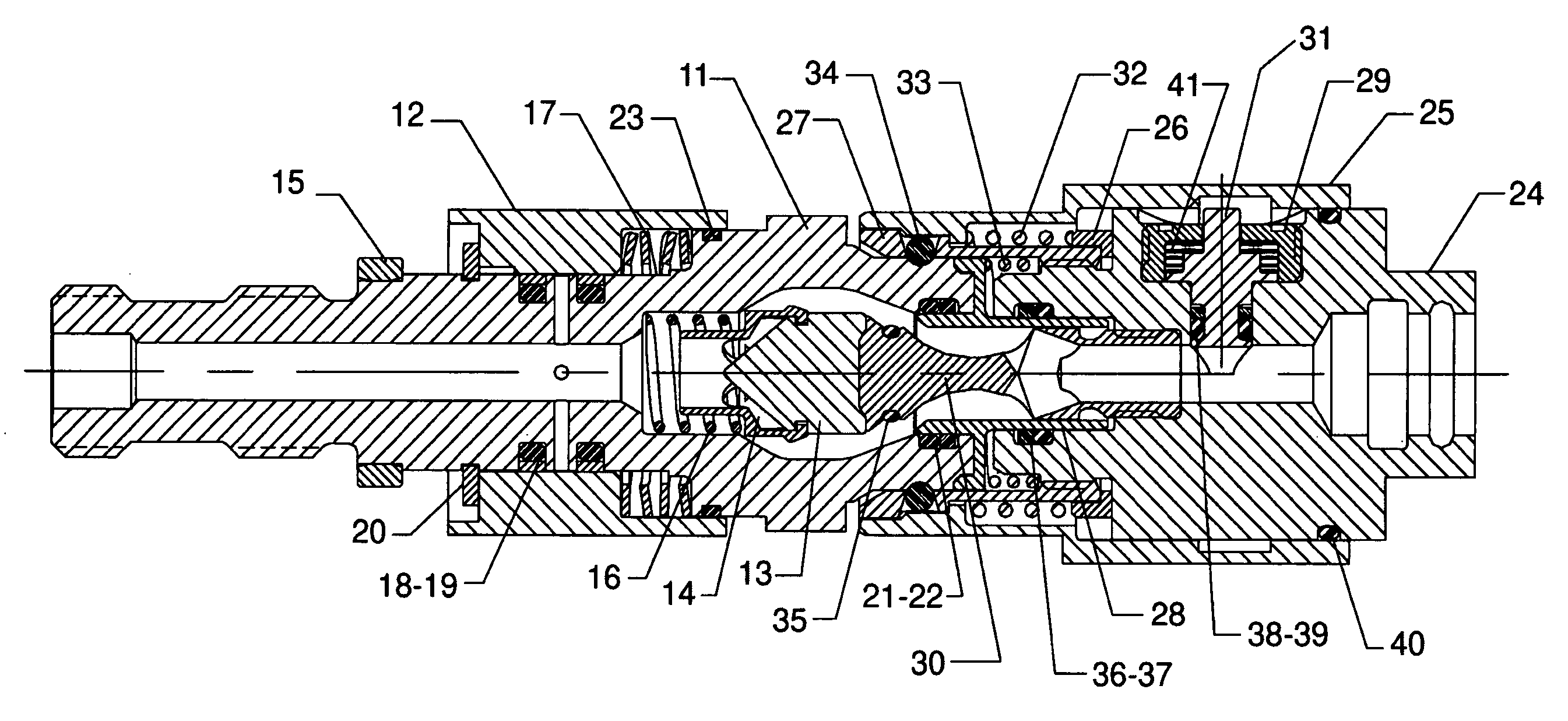
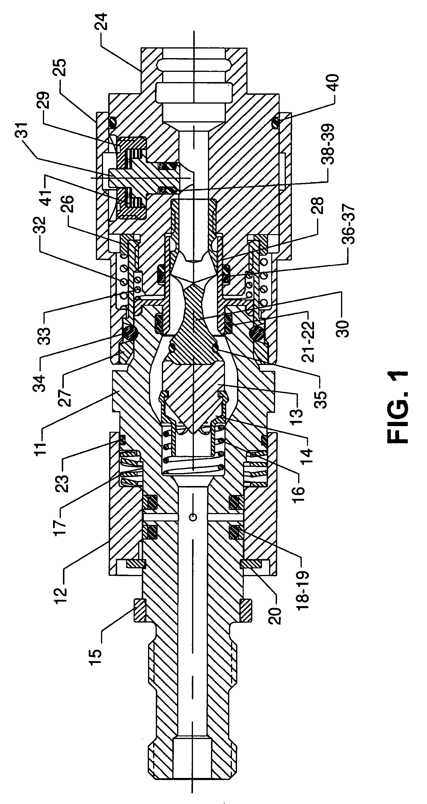
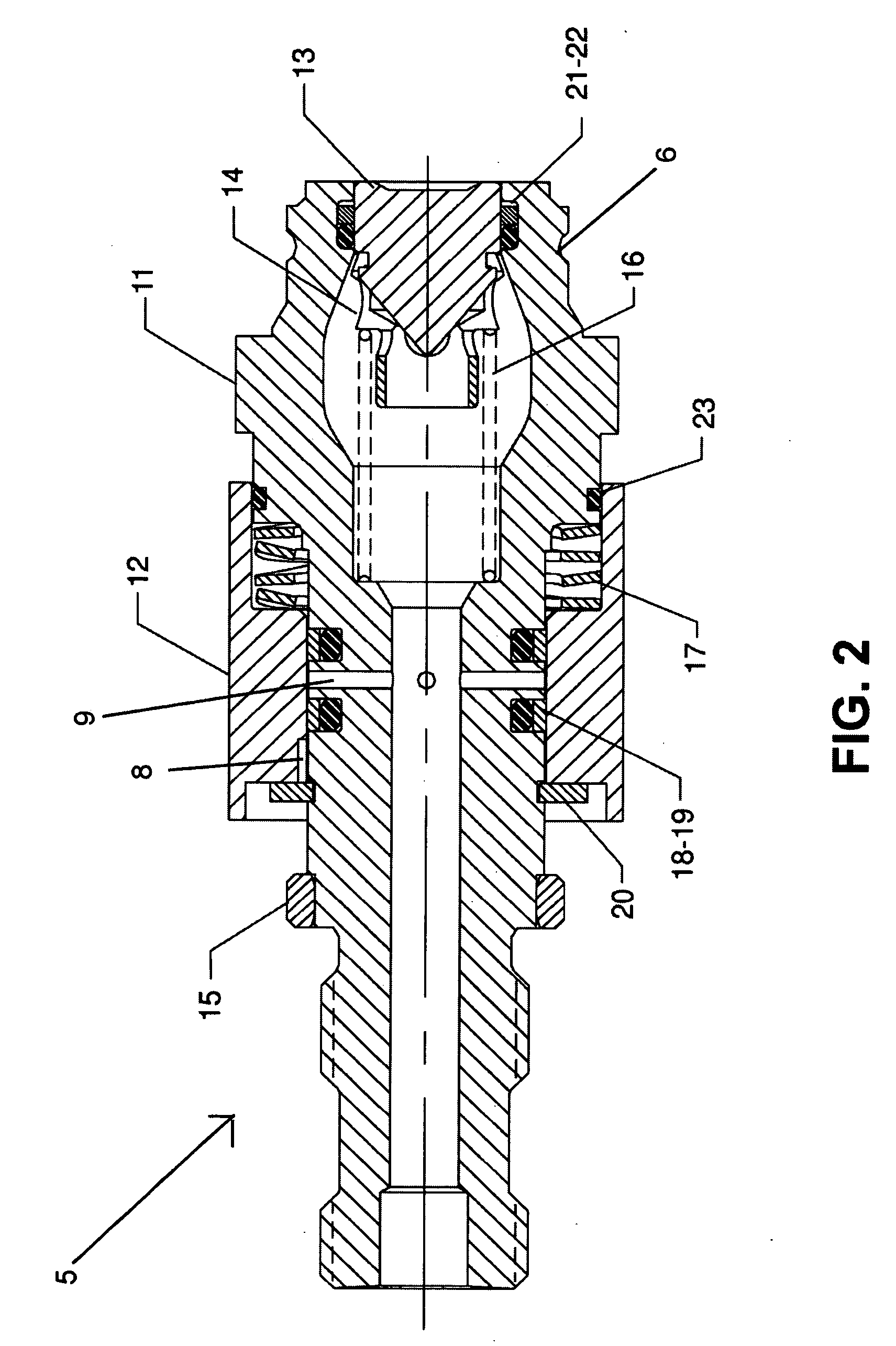
[0022] Referring to the accompanying drawings, it will be seen that the quick-disconnect of the preferred embodiment comprises a nipple 5 and a coupler 10 which are designed to mate together as shown in FIG. 1. As best shown in FIG. 2, the nipple 5 comprises a body 11 upon which there resides a pressure relief slide or sleeve 12 and within which there resides a poppet 13. Also within the body 11 is a poppet retainer 14 and a compression spring 16. Slide 12 also engages a compression spring 17 which resides between the radial surface of body 11 and the inside surface of the slide. Other components of nipple 5 include a bushing 15, a retainer ring 20 and a plurality of o-rings 18, 19 and 21-23. A particularly novel aspect of the nipple 5 is the radially directed orifice 9 which exits at and is normally covered by slide 13, in which there is a drilled escape hole 8 where the slide normally bears against retainer ring 20. Nipple 5 also has a ball groove 6.

[0023] Referring to FIG. 3, it...


PUM


Abstract

A quick-disconnect, the nipple portion of which has a pressure relief path and a coupler portion of which has a safety lock. The nipple portion is provided with a spring-loaded sleeve which covers the relief flow path when not engaged. The sleeve is hand driven against the spring load to expose the flow relief passage. Any pressure in the quick-disconnect is then discharged to atmosphere. The coupler portion incorporates a piston that is pressure activated to block the motion of a disconnecting sleeve. The piston is moved to the unlocked position by a wave spring when the pressure is removed. These features are packaged in a small volume for use in systems where space is limited. The quick-disconnect is designed and fabricated with materials that can withstand a proof pressure of 20,000 PSI. Such capabilities are especially useful in aircraft systems with a supply pressure of up to 5,000 PSI. The pressure relief assures the quick-disconnect can be relieved of any residual pressure up to 5,000 PSI before it is uncoupled and the lock assures that it can not be uncoupled without pressure relief.

Description

BACKGROUND OF THE INVENTION [0001] 1. Field of the Invention [0002] The present invention relates generally to quick-disconnects and more specifically to a quick-disconnect having a spring-loaded sleeve that allows pressure relief and a pressure activating locking piston in a small envelope for high-pressure systems. [0003] 2. Background Art [0004] Fluid flow quick-disconnects are well-known devices commonly used to interconnect one flexible pipe or hose to another flexible pipe or hose for transferring fluids. Virtually all quick-disconnects consist of a mating pair of male and female annular connectors referred to as a nipple and a coupler. Quick-disconnects allow expedient connection and disconnection of such hoses or pipes by a simple mechanical release mechanism. When the quick-disconnect is separated, each component provides a sealing feature designed to allow little or no leakage of the fluid. [0005] Each member of the quick-disconnect is designed to connect with the correspo...

Claims


Application Information

Patent Timeline
IPC IPC(8): F16L37/36
CPCF16L2201/20F16L37/34Y10T137/87973
Inventor CONWAY, TIMOTHY J.
Owner PREECE
Learn More