Plunger Lift Apparatus

a technology of lifting apparatus and plunger, which is applied in the direction of fluid removal, earthwork drilling and mining, and wellbore/well accessories, etc., can solve the problems of sleeve falling back down the production string, loss of fluid load being lifted by the plunger, and opening of the passage, so as to improve the appreciation of the contribution to the art

Inactive Publication Date: 2007-10-25
SCHNEIDER GLENN +1
View PDF14 Cites 25 Cited by
  • Summary
  • Abstract
  • Description
  • Claims
  • Application Information

AI Technical Summary

Benefits of technology

[0009] There has thus been outlined, rather broadly, the more important features of the invention in order that the detailed description thereof that follows may be better understood and in order that the present contribution to the art may be better appreciated.
[0010] Numerous objects, features and advantages of the present invention will be readily apparent to those of ordinary skill in the art upon a reading of the following detailed description of presently preferred, but nonetheless illustrative, embodiments of the present invention when taken in conjunction with the accompanying drawings. The invention is capable of other embodiments and of being practiced and carried out in various ways. Also, it is to be understood that the phraseology and terminology employed herein are for the purpose of descriptions and should not be regarded as limiting.

Problems solved by technology

In this design, the detachable valve member must be lighter or less dense than the sleeve, so that the detachable valve member is not easily dislodged from the sleeve during lift, which would result in opening of the passage and a loss of fluid load being lifted by the plunger.
Further, it would cause the sleeve to fall back down the production string until the detachable valve member was once again reseated in the sleeve.
A few drawbacks exist with this design, one being, the detachable valve member being lighter or less dense than the sleeve it needs an appreciable amount of time to reach the bottom of the well prior to dropping the sleeve.
The greater amount of time needed between dropping the detachable valve member and dropping the sleeve reduces the cycle frequency of the plunger, which results in an increase in time needed to unload fluid from the well.
A second drawback, is the requirement of using a less dense or light detachable valve member to ensure the valve member remains captured by the seat requires the use of a more dense or heavier sleeve.
A heavy sleeve increases wear on well equipment, such as a bottom hole spring and or the surface lubricator springs, from repetitive impact by the heavy sleeve.

Method used


Image

  • Plunger Lift Apparatus
  • Plunger Lift Apparatus
  • Plunger Lift Apparatus

Examples


Embodiment Construction

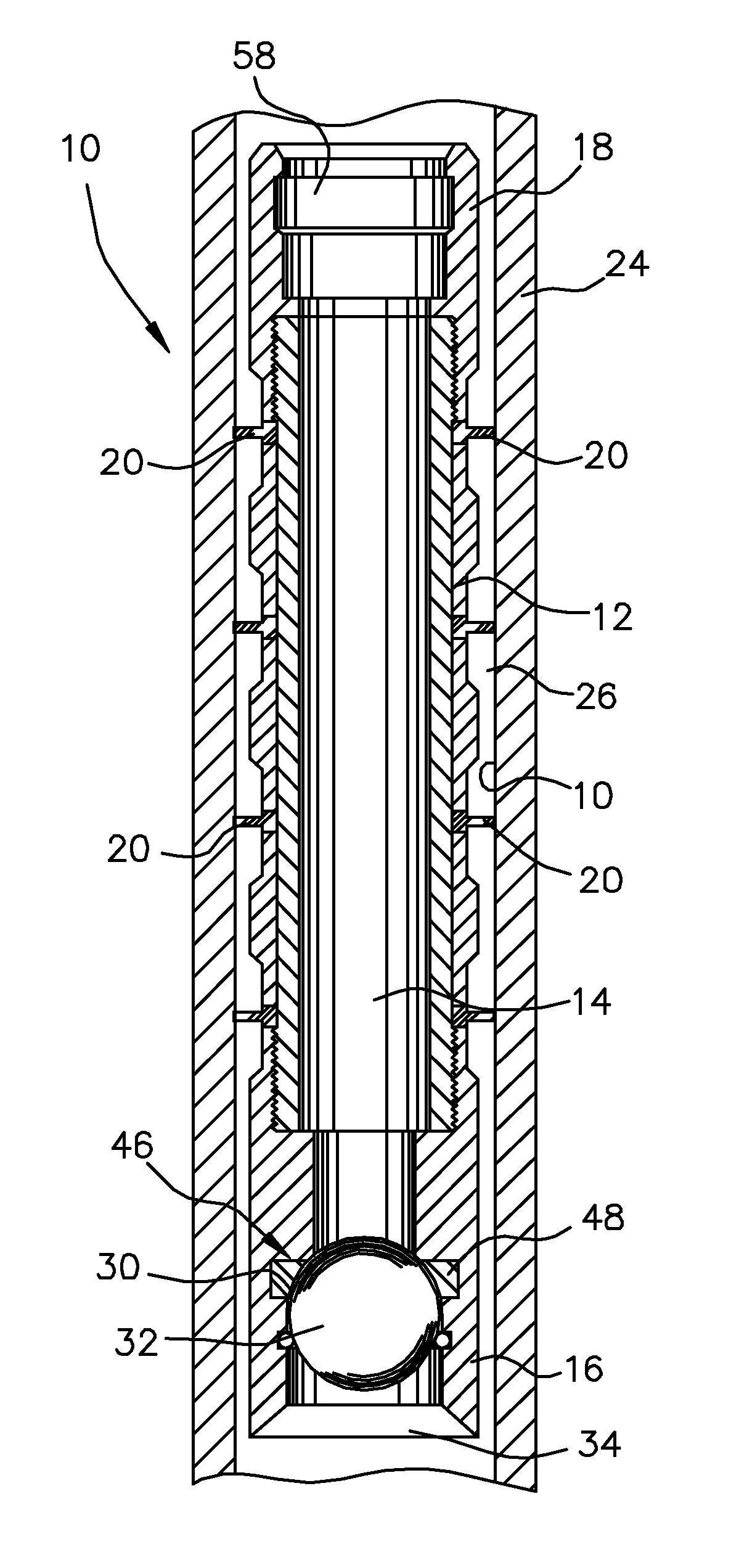
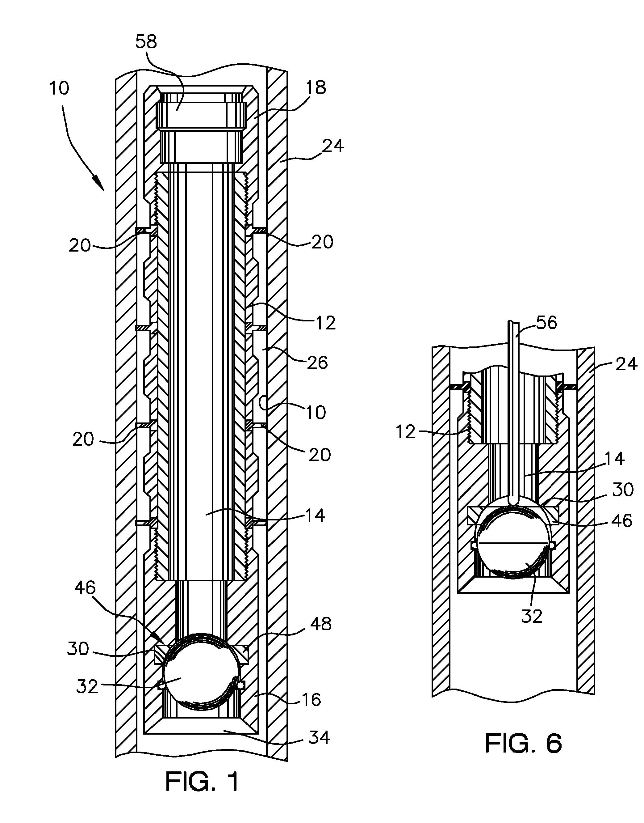
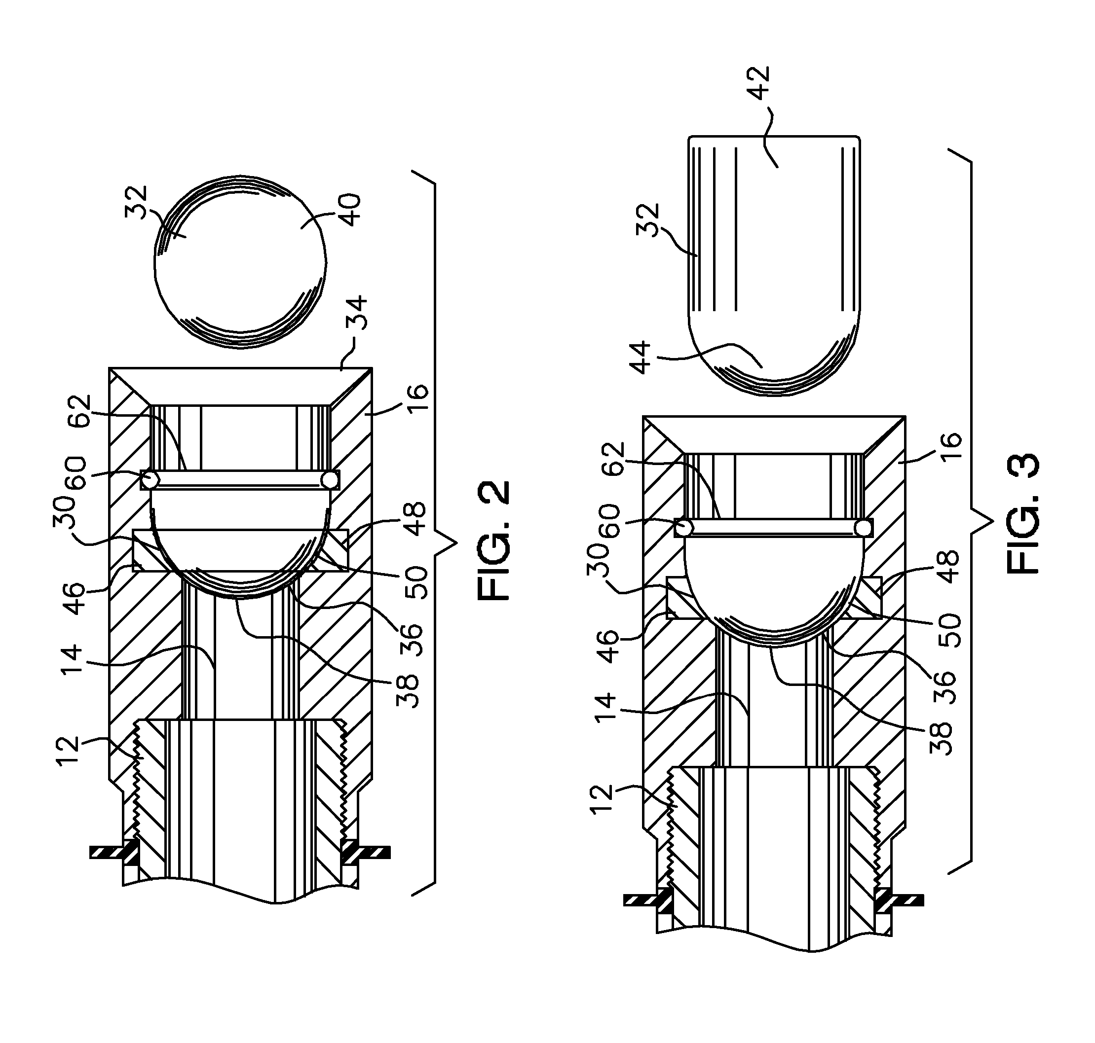
[0021] Referring now to the drawings, the plunger 10 of this invention has an improved construction affording the plunger an increased cycle frequency and cycle efficiency in lifting fluid that has accumulated in a production string of well. The improved construction allows the use of a more dense detachable valve member and a less dense sleeve, as will be further described in detail below.

[0022] With reference now to FIG. 1, the plunger 10 includes a sleeve 12 having a through passage 14 that extends longitudinally through the sleeve from a first, bottom end, 16 to a second, top end 18. The sleeve 12 may comprises several sections coupled together as shown or can be made unitary. The second end 18 can define an internal fishing neck 58.

[0023] The sleeve 12 carries sealing elements 20 which are engagable with the inner surface 22 of a production string 24 sealing the annulus 26 between the sleeve and the inner surface of the production string from fluid flow. However, the sleeve 1...


PUM


Abstract

A plunger of improved construction for reciprocating in a production string of a gas or oil well to remove fluid from the well. The plunger includes a sleeve having a through passage extending longitudinally from a first end to a second end, the second end forming a seat, a sealing means carried by the sleeve for engaging the inner surface of the production string, a detachable valve member releasably received by the seat to seal the through passage, and a catch positioned to releasably couple the detachable valve member to the sleeve within the seat. The catch retaining the detachable valve member until the detachable valve member is impacted at the surface of the well by a trip rod. The improved construction provides for the use of a heavier or more dense detachable valve member and a lighter or less dense sleeve than previously used in prior plungers, which results in a plunger having an increased efficiency and a greater cycle frequency.

Description

FIELD OF THE INVENTION [0001] The present invention relates generally to a plunger apparatus for use in plunger lift operations of an oil or gas well to remove fluid that has accumulated within the well resulting in reduced well production. More particularly, relating to a plunger having an improve construction which increases cycle frequency and plunger performance. BACKGROUND OF THE INVENTION [0002] In general, plunger lift is an artificial-lift method principally used in gas wells to unload formation fluid that has accumulated in the well production string. However, plunger lift can be used in oil wells. An automated system mounted on the wellhead controls the well on an intermittent flow regime. When the well is shut-in, a plunger drops down the production string. When the control system opens the well for production, the plunger and a column of fluid are carried up the tubing string. The surface receiving mechanism detects the plunger when it arrives at surface and, through the...

Claims


Application Information

Patent Timeline
Patent Type & Authority Applications(United States)
IPC IPC(8): E21B43/00
CPCE21B43/121
Inventor SCHNEIDER, GLENNMASON, KELLY
Owner SCHNEIDER GLENN
Why Eureka
Try Eureka