Fixing device for image forming apparatus and fixing method

Inactive Publication Date: 2007-10-25
KK TOSHIBA +1
View PDF11 Cites 47 Cited by
  • Summary
  • Abstract
  • Description
  • Claims
  • Application Information

AI Technical Summary

Benefits of technology

[0009] Accordingly, an advantage of the present invention is to provide a fixing device for an image forming apparatus for performing heat fixation with a heat roller in which a surface of a resilient member layer is covered with a heat conductive layer, wherein even though a space for releasing expansion of the resilient member layer is provided, a pressing force of a pressure roller with respect to the heat roller is varied to prevent a load from concentrating to both end portions of the heat roller so that a long lifetime of the heat roller is achieved.
[0010] To achieve the above advantage, one aspect of the present invention is to provide a

Problems solved by technology

Therefore, when heating the heat roller, the hardness of the heat roller in the longitudinal direction becomes non-uniform due to the difference in coefficient of thermal expansion between the resilient member layer and the metal conductive layer.
The non-uniformity in hardness of the heat roller in the longitudinal direct

Method used


Image

  • Fixing device for image forming apparatus and fixing method
  • Fixing device for image forming apparatus and fixing method
  • Fixing device for image forming apparatus and fixing method

Examples


first embodiment

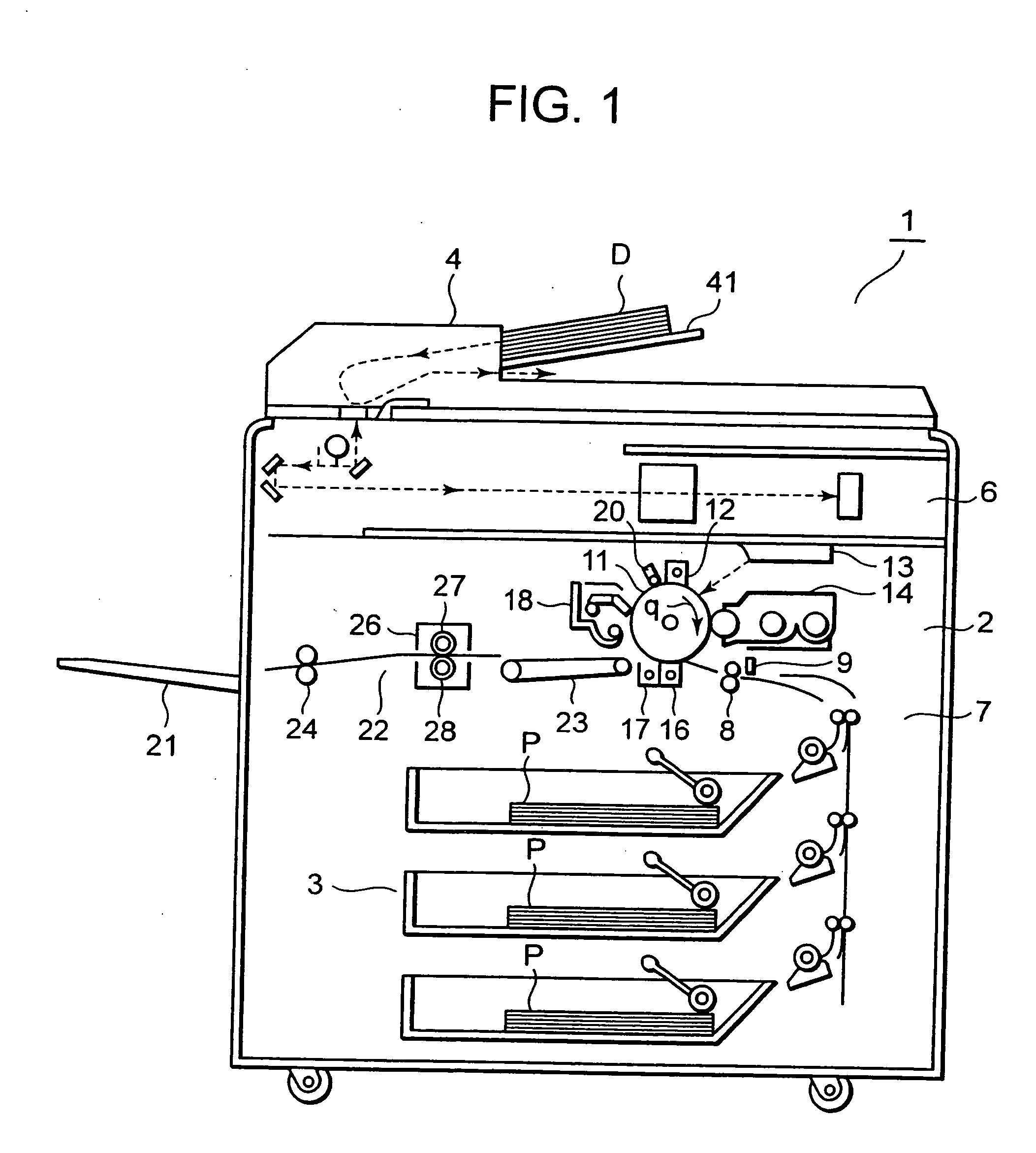
[0021] Referring now to the attached drawings, the present invention will be described in detail. FIG. 1 is a schematic block diagram showing an image forming apparatus 1 including a fixing device 26 according to one embodiment of the present invention mounted thereon. The image forming apparatus 1 includes a cassette mechanism 3 for supplying a paper P as a fixed medium to an image forming unit 2, and a scanner unit 6 for reading an original document D supplied by an automatic document feeding device 4 on an upper surface thereof. A registration roller 8 is provided on a carrier path 7 from the cassette mechanism 3 to the image forming unit 2.

[0022] The image forming unit 2 includes a charging device 12 for charging a photoconductive drum 11 uniformly according to the direction of rotation of the photoconductive drum 11 in sequence as indicated by an arrow q, a laser exposure device 13 for forming a latent image on the basis of image data from the scanner unit 6 on the charged phot...

second embodiment

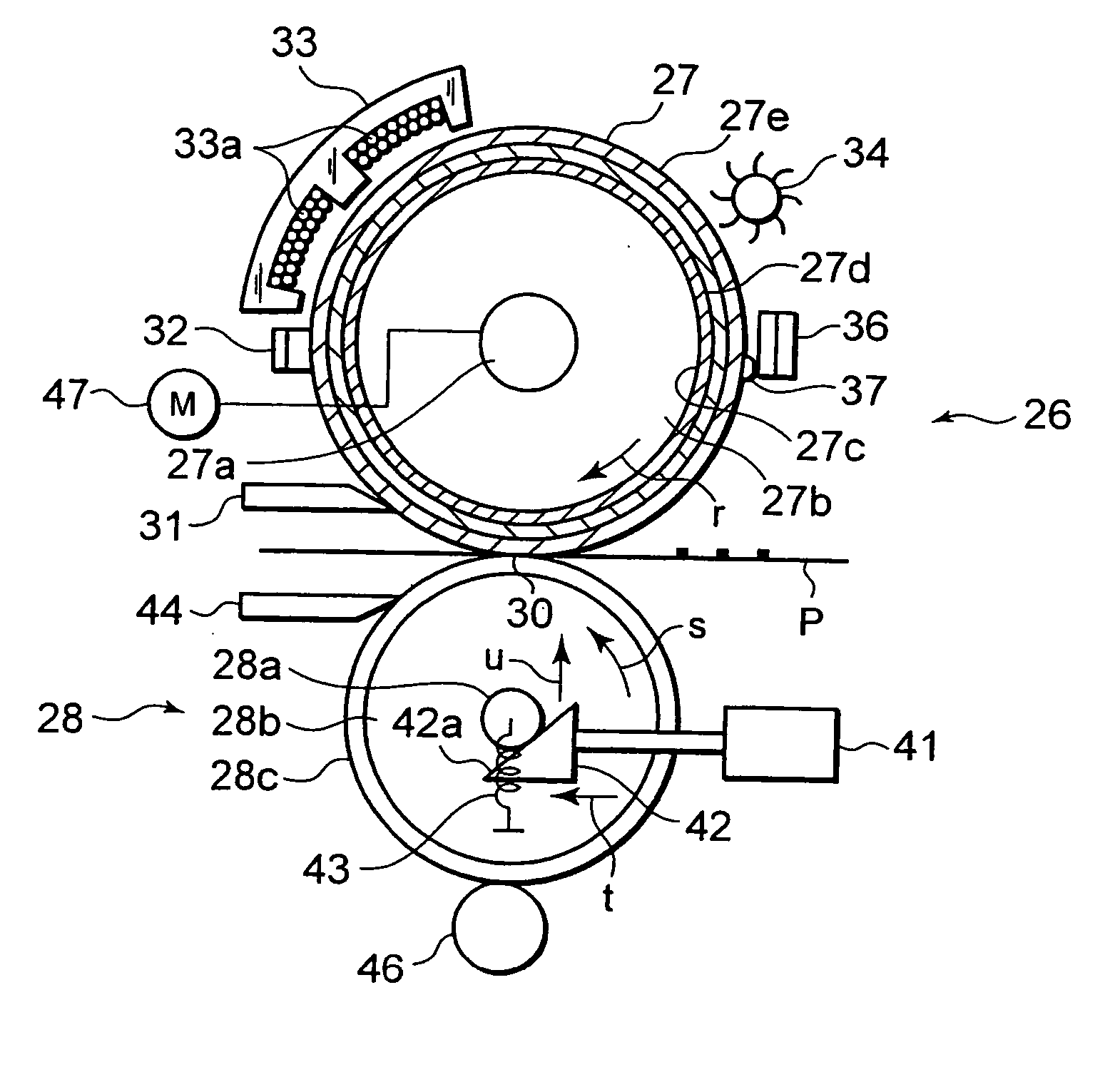
[0045] A fixing device 126 in the second embodiment includes the motor 47 on the side of the shaft member 28a of the pressure roller 28 as shown in FIG. 5, and the heat roller 27 is driven by the pressure roller 28. When the solenoid 41 is in OFF, the cam portion 42a of the push-up cam 42 pushes the shaft member 28a of the pressure roller 28 in the direction indicated by the arrow u so that the pressing force of the pressure roller 28 with respect to the heat roller 27 becomes 5 kg. When the solenoid 41 is ON, the cam portion 42a of the push-up cam 42 pushes up the shaft member 28a of the pressure roller 28 in the direction indicated by the arrow u so that the pressing force of the pressure roller 28 with respect to the heat roller 27 becomes 40 kg.

[0046] An encoder 51 for detecting the number of rotations of the shaft member 27a is connected to one end of the shaft member 27a of the heat roller 27. The number of rotations of the shaft member 27a detected by the encoder 51 is suppli...

fourth embodiment

[0064] In the fourth embodiment, as shown in FIG. 8, a reference warming up time is stored in a memory 448a, for example, in a control device 448. For example, when the room temperature is, for example, 25° C., a time period of 30 seconds from a moment when the power source is turned ON until the temperature of the heat roller 27 reaches 170° C. which is the warming up completion temperature is stored. Then, the memory 448a further stores, for example, 60 seconds, as a time period from the completion of the warming up until the foam rubber layer 27b reaches a predetermined expansion. A calculating unit 448b in the control device 48 converts the warming up time corresponding to the respective room temperature from the reference warming up time.

[0065] When the warming up is started, the pressing force of the pressure roller 28 with respect to the heat roller 27 is set to 5 kg. When the room temperature at the time of starting the warming up is, for example, 25° C., the warming up time...


PUM


Abstract

A fixing device for an image forming apparatus according to the present invention is configured in such a manner that both end portions of a form rubber layer are formed so as to be thicker than a center portion thereof for absorbing expansion of the foam rubber layer by a space between the foam rubber layer and a metal conductive layer. Accordingly, the hardness of a heat roller at the time of fixation becomes substantially uniform over the entire length thereof in the longitudinal direction. A pressure roller is out of contact with the heat roller until warming up is completed, and the pressure roller is brought into pressure contact with the heat roller after the heat roller has reached a warming up complete temperature, so that a load applied to both end portions of the heat roller is alleviated.

Description

BACKGROUND OF THE INVENTION [0001] 1. Field of the Invention [0002] The present invention relates to a fixing device for an image forming apparatus mounted to the image forming apparatus such as a copying machine, a printer, a facsimile for thermally fixing a toner image. [0003] 2. Description of the Background [0004] As a fixing device to be used for an image forming apparatus such as copying machines, printers, and so on of an electrophotographic type, there is a fixing device that inserts a sheet paper through a nip formed between a heat roller and a pressure roller and fixes a toner image by heat and pressure. Recent years, as a heating type fixing device, there is a device that covers a surface of a resilient member layer formed on the outside of a core member of the heat roller with a metal conductive layer and heats the metal conductive layer with an induction heating system. The induction heating system is a system to supply a predetermined electric power to an induction hea...

Claims


Application Information

Patent Timeline
IPC IPC(8): H05B6/14
CPCH05B6/145
Inventor TSUEDA, YOSHINORIKINOUCHI, SATOSHITAKAGI, OSAMUSONE, TOSHIHIRO
Owner KK TOSHIBA
Why Eureka
Try Eureka