
Tail wire cutting method and bonding apparatus

Inactive Publication Date: 2007-10-25
SHINKAWA CO LTD
View PDF14 Cites 26 Cited by
  • Summary
  • Abstract
  • Description
  • Claims
  • Application Information

AI Technical Summary

Benefits of technology

[0016]Accordingly, the object of the present invention is to provide a tail wire cutting method and bonding apparatus that effects tail wire cutting without subjecting the tail wire to large pulling forces and that prevents wire bending when cutting of the tail wire is performed.
[0019]closing the clamper and causing the capillary together with the clamper to make one of arc-shaped reciprocating oscillation movement and circular oscillation movement on a curved surface having an apex thereof at the first height, thus degrading a rigidity of a connecting portion between the tail wire and the second bonding point; then
[0035]a movement on a curved surface means for closing the clamper by the clamper opening and closing device and causing the capillary together with the clamper, by the movement mechanism, to make one of arc-shaped reciprocating oscillation movement and circular oscillation movement on a curved surface having an apex thereof at the first height, thus degrading a rigidity of a connecting portion between the tail wire and the second bonding point, after raising the capillary to the first height by the first capillary raising means,
[0049]The present invention provides the benefits that a tail wire is cut without subjecting it to any large pulling force, and wire bending that would occur when cutting tail wires is prevented.

Problems solved by technology

Tail wire 8 bending is a problem, causing ball shape defects due to electrical discharges or the like during bonding to the next pad 3.
Thus, the problem is that this art cannot be used for short tail wire lengths required in today's high-speed bonding apparatuses.

Method used


Image

  • Tail wire cutting method and bonding apparatus
  • Tail wire cutting method and bonding apparatus
  • Tail wire cutting method and bonding apparatus

Examples


Embodiment Construction

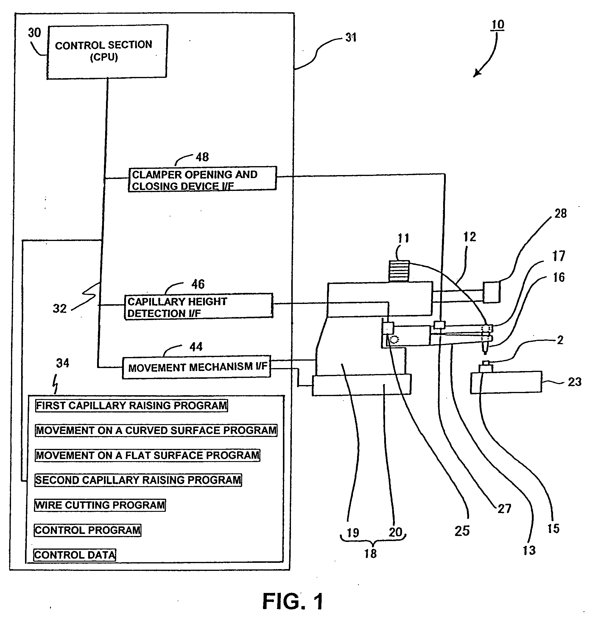
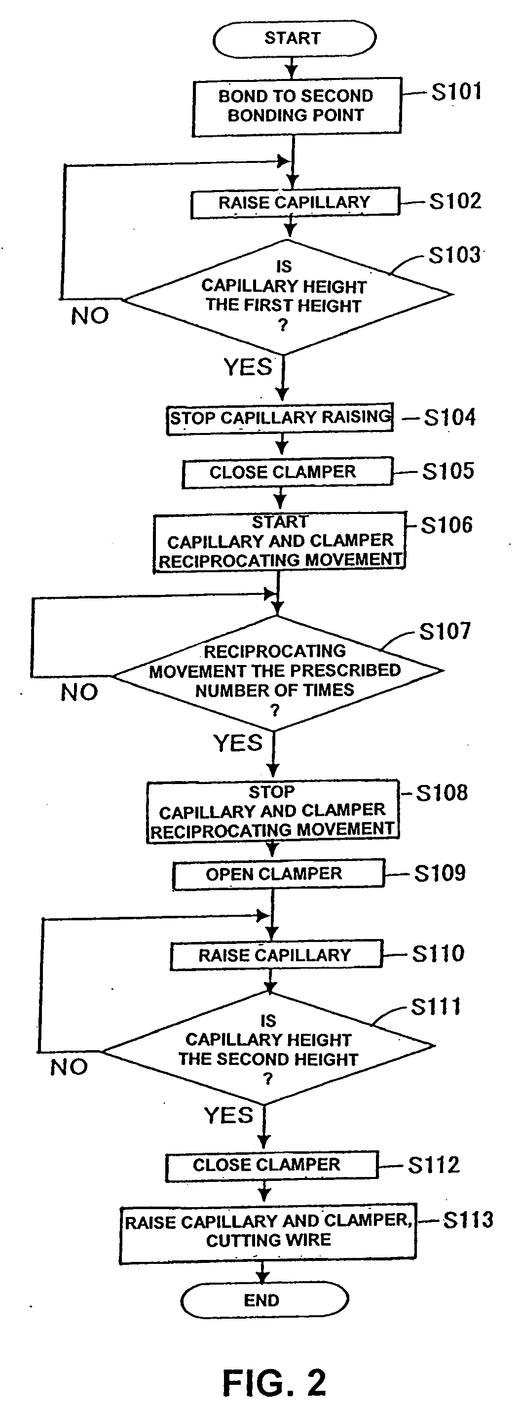
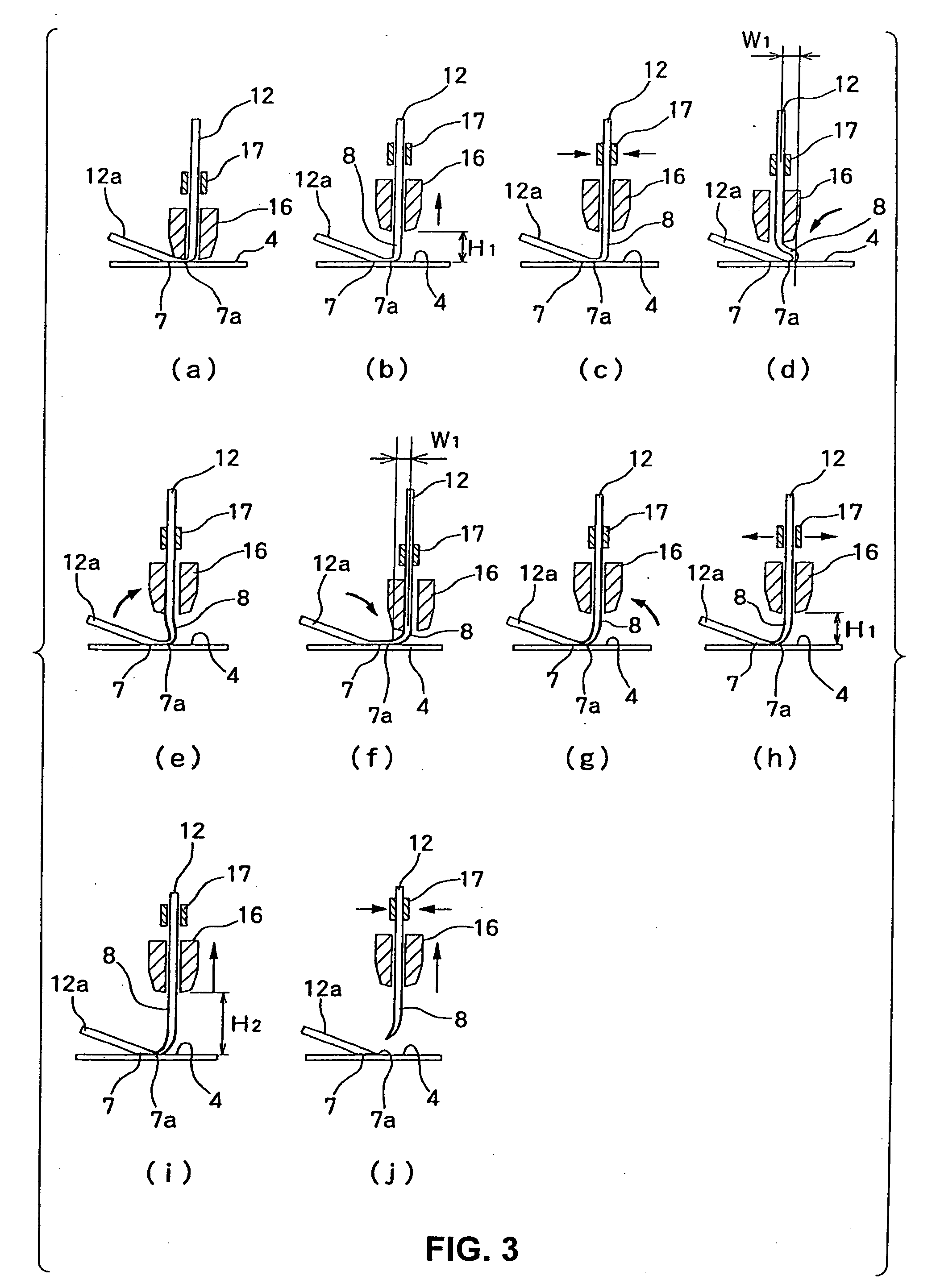
[0063]Hereinafter, preferred embodiments of the present invention will be described with reference to FIGS. 1 to 5. FIG. 1 is a diagram representing the configuration of a wire bonding apparatus that executes a tail wire cutting method and program of to the present invention. FIG. 2 is a flowchart of a tail wire cutting method of the present invention. FIG. 3 is an explanatory diagram of the steps for cutting a tail wire according to the method and program of the present invention. FIG. 4 is an explanatory diagram of the reciprocating oscillation movement of a capillary and clamper in the present invention. FIG. 5 is a perspective view of the reciprocating oscillation movement, on a curved surface, of a capillary and clamper in the present invention.

[0064]As seen from FIG. 1, in a wire bonding apparatus 10, a bonding head 19 is installed on an XY table 20, and a bonding arm 13, the tip whereof being movable in the Z direction by a motor, is provided on the bonding head 19. A capilla...


PUM

PropertyMeasurementUnit
Heightaaaaaaaaaa

Abstract

A tail wire cutting method and bonding apparatus executing the same, in which a capillary raised to a predetermined height and a clamper disposed above the capillary and gripping a wire are caused to make reciprocating oscillation movement on, for instance, a circular arc that has an apex at the above-described predetermined height, thus forming (minute) cracks in a portion between the tail wire and a bonding end of a bonding point, and then cutting of a tail wire sticking out of the tip end of the capillary is executed by way of raising the capillary and clamper.

Description

BACKGROUND OF THE INVENTION[0001]The present invention relates to a tail wire cutting method and a bonding apparatus executing the method.[0002]Assembly processes for ICs (integrated circuits) and other semiconductor devices include a wire bonding process for connecting semiconductor chips and lead frames with wires; and for this wire bonding step, wire bonding apparatuses and bump bonding apparatuses are used typically. In the wire bonding process, connections are made, as shown in FIG. 10, with connecting wires 12a between pads 3 on a semiconductor chip 2 and leads 4 of a lead frame 15, all of that being part of a work 14.[0003]FIG. 11 shows bonding actions in each one of the steps in the above-described bonding process conventionally employed. In the following description, a bonding process taken in a wire bonding apparatus will be described.[0004](1) In step (a), a ball 5 is formed at the tip end of a wire 12, and a capillary 16 is moved above a pad 3 (first bonding point).[0005...

Claims


Application Information

Patent Timeline
IPC IPC(8): A47J36/02
CPCH01L2224/45144H01L2924/01033H01L2224/48247H01L2224/48465H01L2224/48475H01L2224/49171H01L2224/78302H01L2224/85051H01L2224/85181H01L2924/01004H01L2924/01047H01L2924/01051H01L2924/01074H01L2924/01079H01L2924/01082H01L2924/14H01L2924/20752H01L2224/48091H01L2924/01006H01L2924/01005H01L2224/45015H01L24/85H01L24/78Y10S228/904H01L2224/45139H01L24/45H01L2924/00014H01L2924/00H01L2224/78301H01L2224/05554H01L24/48H01L24/49H01L2224/85206H01L2224/78621H01L2924/00011H01L2224/4554H01L2924/01049A61F5/0102A61F5/0193A61F2005/0132A61F2005/0151
Inventor TEI, SHINSUKEMORI, NORIKO
Owner SHINKAWA CO LTD
Features
  • Generate Ideas
  • Intellectual Property
  • Life Sciences
  • Materials
  • Tech Scout
  • Unparalleled Data Quality
  • Higher Quality Content
  • 60% Fewer Hallucinations
Learn More