Communicating with an implanted wireless sensor

Active Publication Date: 2007-10-25
ST JUDE MEDICAL LUXEMBOURG HLDG II S A R L SJM LUX II
View PDF99 Cites 27 Cited by
  • Summary
  • Abstract
  • Description
  • Claims
  • Application Information

AI Technical Summary

Benefits of technology

[0008] The primary goal of aneurysm treatment is to depressurize the sac and to prevent rupture. Endoleaks, whether occurring intraoperatively or postoperatively, can allow the aneurysmal sac to remain pressurized and therefore, increase the chance of aneurysm rupture. The current imaging modalities angio

Problems solved by technology

Endoleaks, whether occurring intraoperatively or postoperatively, can allow the aneurysmal sac to remain pressurized and therefore, increase the chance

Method used


Image

  • Communicating with an implanted wireless sensor
  • Communicating with an implanted wireless sensor
  • Communicating with an implanted wireless sensor

Examples


Embodiment Construction

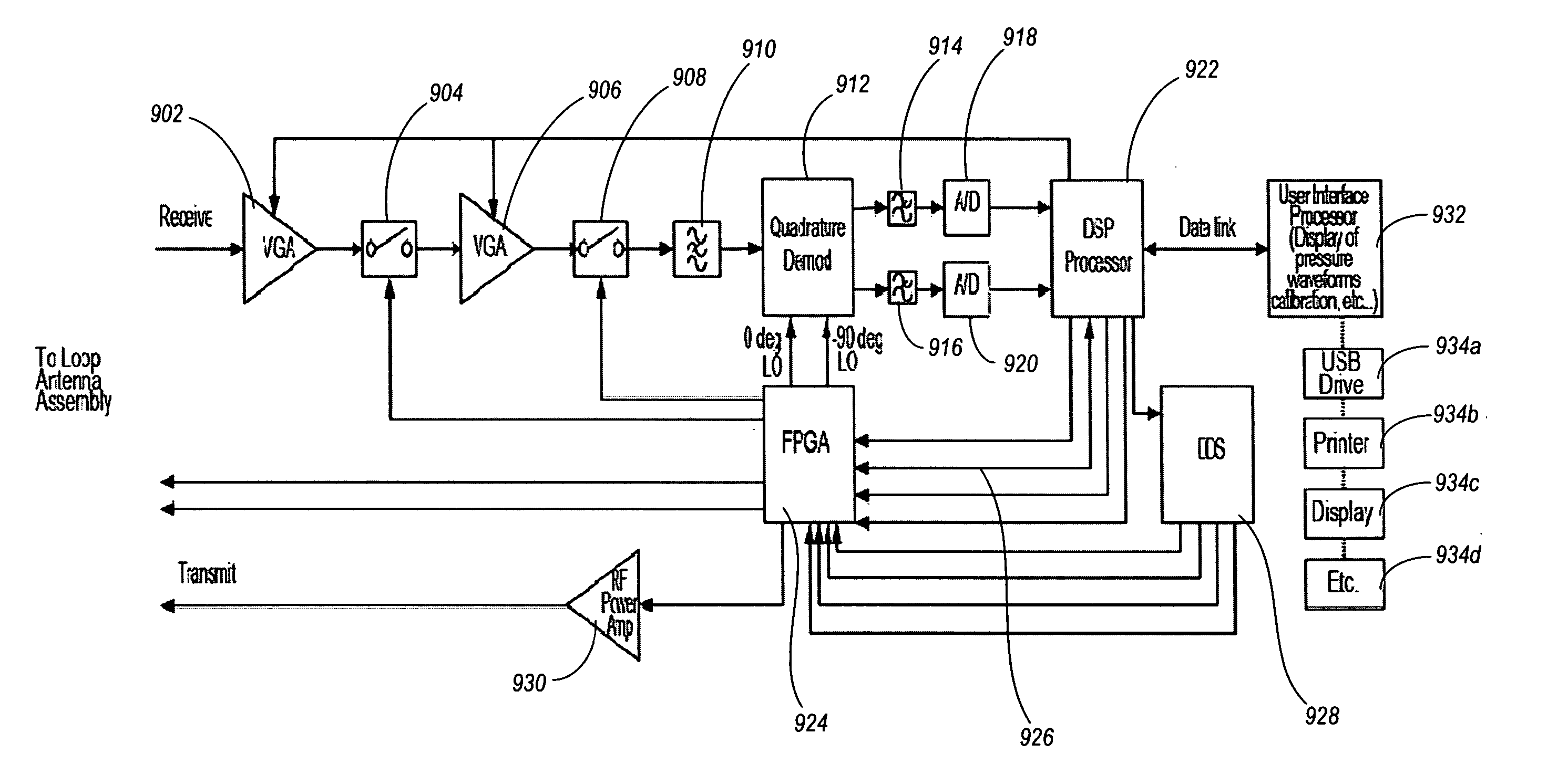
[0028] The present invention is directed towards a system and method for communicating with a wireless sensor. Briefly described, the present invention determines the resonant frequency of the sensor by adjusting the phase and frequency of one or more energizing signals until the frequency of this signal locks to the resonant frequency of the sensor. The frequency of the energizing signal can be adjusted using a group phase delay operation. The system energizes the sensor with a low duty cycle, gated burst of RF energy at a predetermined set of frequencies and a predetermined amplitude. In some embodiments, the set of frequencies includes three different energizing signals at different frequencies which are transmitted separately. The signals induce current in the sensor that can be used to track the resonant frequency of the sensor. The system receives the ring down response of the sensor as sensor signals at three different frequencies and determines the resonant frequency of the ...


PUM


Abstract

Aspects of the present invention determine the resonant frequency of a sensor by obtain sensor signals in response to three energizing signals, measure the phase of each sensor signal, and using a group phase delay to determine the resonant frequency. The phase difference between the first and second signal is determined as a first group phase delay. The phase difference between the second and third signal is determined as a second group phase delay. The first group phase delay and second group phase delay are compared. Based on the comparison, the system may lock on the resonant frequency of the sensor or adjust a subsequent set of three energizing signals.

Description

RELATED APPLICATIONS [0001] This application is a continuation-in-part of U.S. application Ser. No. 11 / 276,571 entitled “Communicating with an Implanted Wireless Sensor” filed Mar. 6, 2006, which is a continuation-in-part of U.S. application Ser. No. 11 / 105,294 entitled “Communicating with an Implanted Wireless Sensor” filed Apr. 13, 2005, which claims priority to U.S. Provisional Application No. 60 / 623,959 entitled “Communicating with an Implanted Wireless Sensor” filed Nov. 1, 2004, all of which are incorporated herein by reference. This application also claims priority to U.S. Provisional Application No. 60 / 782,313 filed Mar. 14, 2006, which is also incorporated herein by reference.TECHNICAL FIELD [0002] The present invention is directed in general to communicating with a wireless sensor, and in particular to communicating with a wireless sensor implanted within the body to measure a physical condition. BACKGROUND [0003] Wireless sensors can be implanted within the body and used ...

Claims


Application Information

Patent Timeline
IPC IPC(8): G01R35/00
CPCA61B5/0031A61B5/073A61B5/02014A61B2560/0219A61B5/076
Inventor MILLER, DONALDELLIS, MICHAELALLEN, MARK
Owner ST JUDE MEDICAL LUXEMBOURG HLDG II S A R L SJM LUX II
Why Eureka
Try Eureka