Sandwich magnetic stir elements for stirring the contents of vessels

a technology of magnetic stir elements and contents, applied in the direction of magnets, magnetic bodies, transportation and packaging, etc., can solve the problems of soft parylene and wear, and achieve the effect of maximizing stirring efficiency, facilitating the manufacture of stirrers, and affecting the movement of greater fluids

Inactive Publication Date: 2007-10-25
V & P SCI
View PDF63 Cites 12 Cited by
  • Summary
  • Abstract
  • Description
  • Claims
  • Application Information

AI Technical Summary

Benefits of technology

[0013] The present invention readily facilitates the disposition of the permanent magnets in magnetic stir elements.
[0014] The present invention particularly facilitates the inclusion of NdFeB permanent magnets in magnetic stir elements that include a PTFE stirrer. NdFeB permanent magnets are preferred for enhancing the responsiveness of the magnetic stir elements because of the very high magnetic field strength of NdFeB permanent magnets. NdFeB has the highest magnetic energy of any material that is currently available for commercial applications. Heretofore, NdFeB permanent magnets have not been included in commercially manufactured magnetic stir elements that include PTFE stirrers because the step of encapsulating the permanent magnets in the prior art PTFE stirrers necessarily heated the PTFE to a temperature that is so high that when NdFeB permanent magnets are encapsulated in the PTFE plastic material the magnetic field strength of the NdFeB permanent magnets is severely diminished.
[0016] The present invention also facilitates the manufacture of stirrers having different and unusual shapes rather inexpensively since the stirrers can be machined, punched or cut with dyes from sheets as opposed to being molded. Another advantage is that by using large “flat” shapes greater fluid movement is affected during stirring. Still another advantage is that the shape can be customized to specifically conform to the inside of a given vessel to thereby maximize stirring efficiency.

Problems solved by technology

However, Parylene is soft and can be worn away by extended use.

Method used


Image

  • Sandwich magnetic stir elements for stirring the contents of vessels
  • Sandwich magnetic stir elements for stirring the contents of vessels
  • Sandwich magnetic stir elements for stirring the contents of vessels

Examples


Embodiment Construction

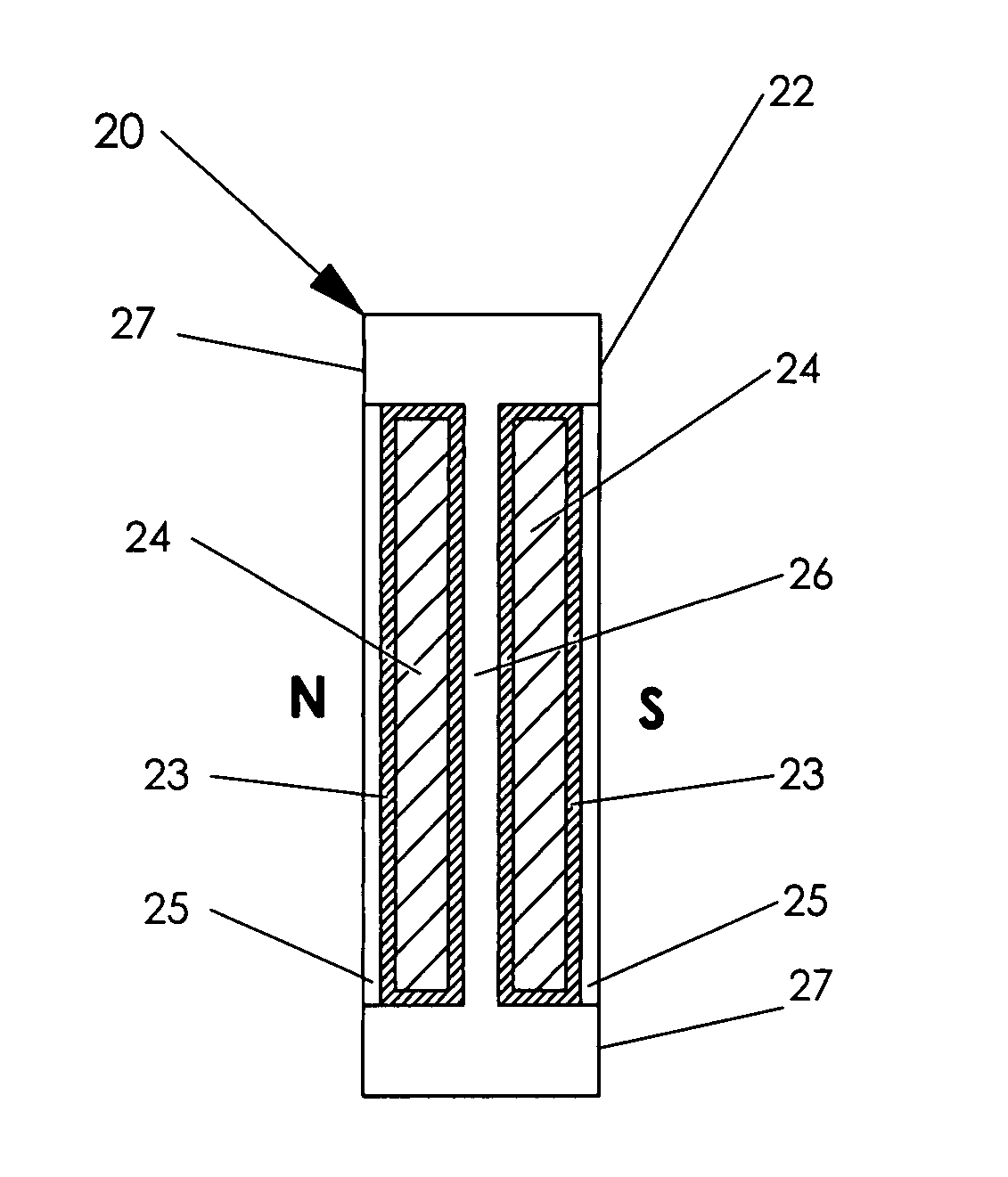
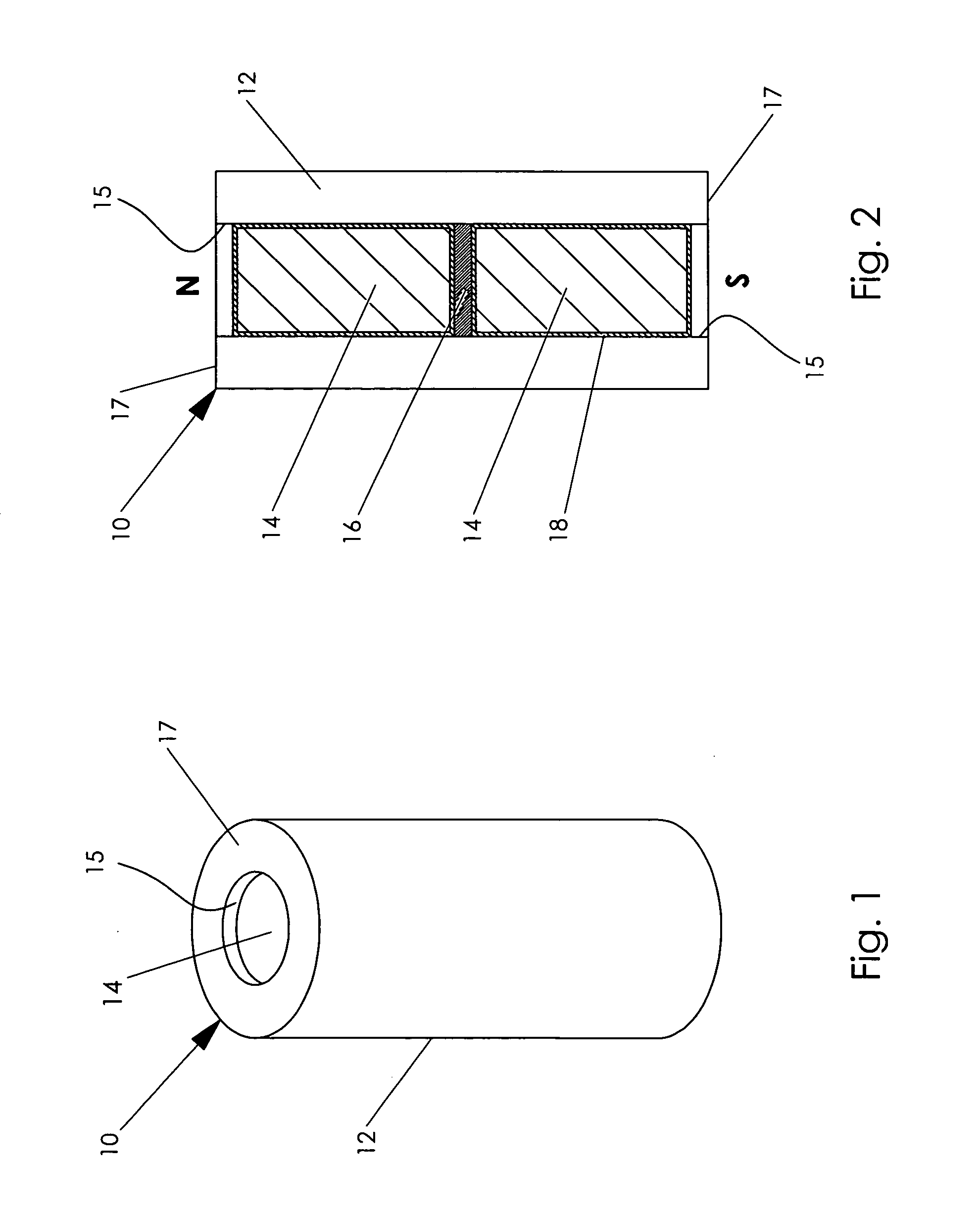
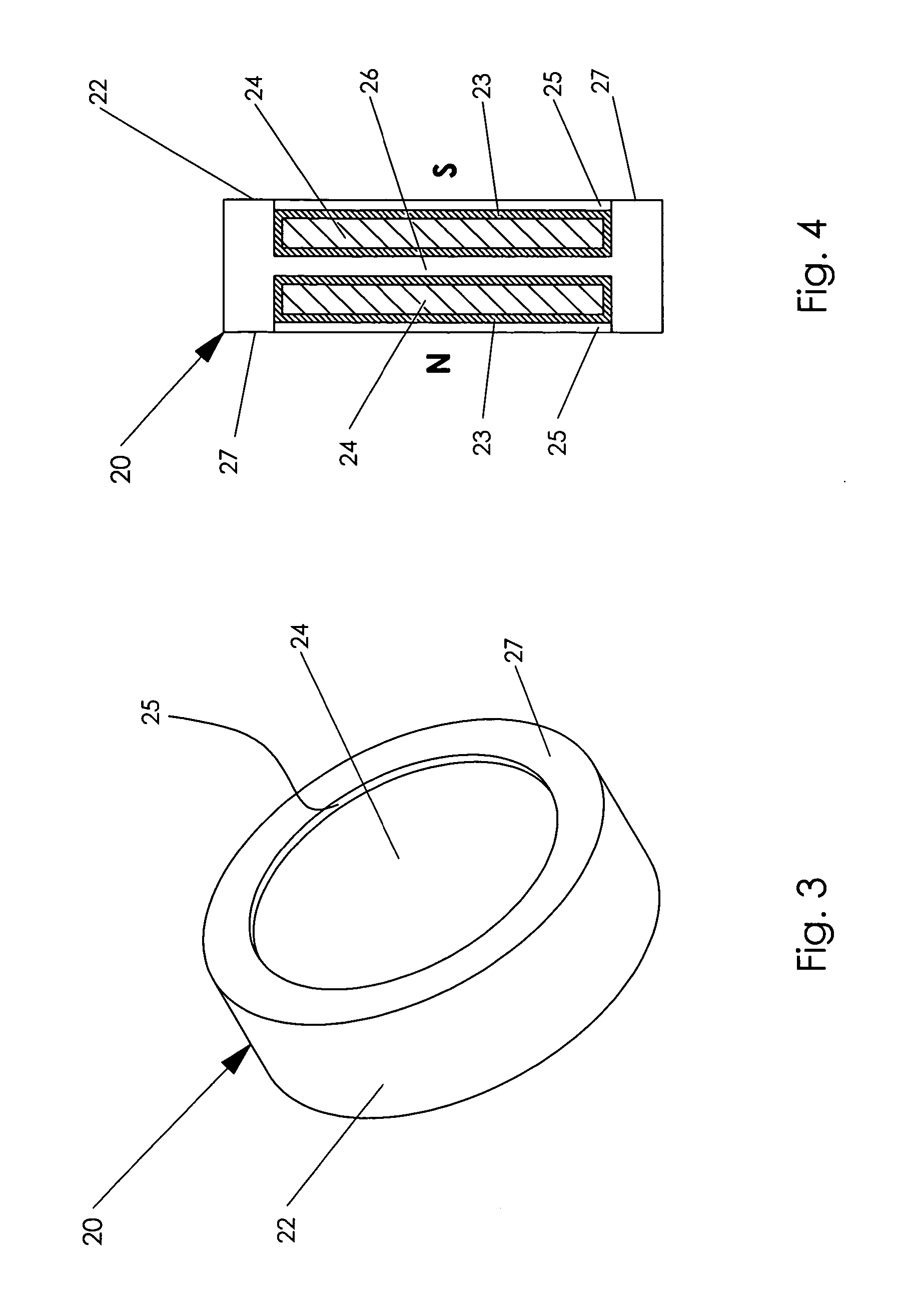
[0027] Referring to FIGS. 1 and 2, one embodiment of an elongated tubular magnetic stir element 10 according to the present invention includes a stirrer 12 of a nonmagnetic, non-reactive, durable material, such as PTFE plastic, and two permanent magnets 14. The stirrer 12 is a tube that is configured for stirring the contents of a vessel. A pair of opposed cylindrical cavities 15 are defined by opposite ends of the tube 12.

[0028] A barrier 16 is inserted into the tube 12 to separate the opposed cylindrical cavities 15. The barrier 16 is a disk that is slightly larger than the inside diameter of the tube 12 that may be either magnetic material or nonmagnetic material. In some embodiments, the barrier disk 16 is stainless steel.

[0029] The permanent magnets 14 are recessed within the pair of cylindrical cavities 15 at a level below the level of the respective surfaces 17 at the opposite ends of the tube 12 that adjoin the pair of cavities 15, to thereby prevent contact between the pe...


PUM


Abstract

A magnetic stir element includes a stirrer of nonmagnetic material that is configured for stirring the contents of a vessel. The stirrer includes a pair of opposed cavities on opposite sides of the stirrer and a barrier that separates the opposed cavities. Magnetized magnetic material is disposed in the pair of opposed cavities to provide a magnetic flux axis for the stirrer. The magnetic material is so magnetized and disposed in the pair of separated opposed cavities that the magnetized magnetic material disposed in one of the pair of separated opposed cavities is magnetically attracted to the magnetized magnetic material disposed in the other of the pair of separated opposed cavities to thereby hold the magnetized magnetic material within the pair of separated opposed cavities.

Description

BACKGROUND OF THE INVENTION [0001] The present invention generally pertains to magnetic stir elements that are used for stirring of the contents of vessels in response to variations in the alignment of magnetic flux lines emanating from a source external to the vessels and is particularly directed to the configuration and composition of magnetic stir elements. [0002] Prior art magnetic stir elements include magnetized magnetic material that is disposed to provide a magnetic flux axis that maintains alignment with the magnetic flux lines emanating from the external source to thereby cause the stir element to tumble, rock back and forth, or spin as the alignment of the externally emanated flux lines vary. One prior art magnetic stir element includes a disk of magnetized magnetic material configured for stirring the contents of a vessel and having oppositely polarized sides. Another prior art magnetic stir element includes an elongated component of magnetized magnetic material that is ...

Claims


Application Information

Patent Timeline
Patent Type & Authority Applications(United States)
IPC IPC(8): B01F13/08
CPCH01F7/021B01F13/0818B01F33/452
Inventor CLEVELAND, PATRICK H.
Owner V & P SCI
Why Eureka
Try Eureka