Method and system for a high power low-coherence pulsed light source

a low-coherence, pulsed technology, applied in the field of tunable light sources, can solve the problems of narrow spectral linewidths, affecting the performance of lasers, and difficult to achieve a range of variable pulse characteristics, so as to maximize the energy extraction efficiency of the laser system, optimize the pulse profile, and maintain pulse-to-pulse stability.

Active Publication Date: 2007-10-25
ELECTRO SCI IND INC
View PDF5 Cites 8 Cited by
  • Summary
  • Abstract
  • Description
  • Claims
  • Application Information

AI Technical Summary

Benefits of technology

[0010]Numerous benefits are achieved using the present invention over conventional techniques. For example, in an embodiment according to the present invention, high power, pulsed lasers suitable for laser processing are provided that utilize a compact architecture that is inexpensive in comparison to lasers with comparable performance characteristics. Moreover, embodiments of the present invention generate short pulses with pulse characteristics that are tunable in real-time while maintaining pulse-to-pulse stability. Furthermore, in an embodiment according to the present invention, optical pulses can be shaped to optimize the pulse profile for particular applications, or to maximize energy extraction efficiency in the laser system. Depending upon the embodiment, one or more of these benefits may exist. These and other benefits have been described throughout the present specification and more particularly below. Various additional objects, features and advantages of the present invention can be more fully appreciated with reference to the detailed description and accompanying drawings that follow.

Problems solved by technology

However, such lasers produce optical pulses with characteristics that are predetermined by the cavity geometry, the mirror reflectivities, and the like and cannot generally be varied in the field without compromising the laser performance.
Using such lasers, it is generally difficult to achieve a range of variable pulse characteristics.
These narrow spectral linewidths can give rise to problems due to Stimulated Brillouin Scattering (SBS) in certain embodiments thereof.
However, conventional low-coherence sources are typically characterized by excessively broad linewidths, for which the optical power available in the spectral band of interest for a particular application is low.
Therefore, low-coherence sources provide limited output power.

Method used


Image

  • Method and system for a high power low-coherence pulsed light source
  • Method and system for a high power low-coherence pulsed light source
  • Method and system for a high power low-coherence pulsed light source

Examples


Embodiment Construction

[0015]According to the present invention, techniques generally related to the field of tunable light sources are provided. More particularly, the present invention relates to a method and apparatus for providing high power pulsed optical sources useful for industrial applications such as trimming, marking, cutting, and welding. Merely by way of example, the invention has been applied to a light source with real-time tunable characteristics including pulse width, peak power, repetition rate, and pulse shape. However, the present invention has broader applicability and can be applied to other optical sources.

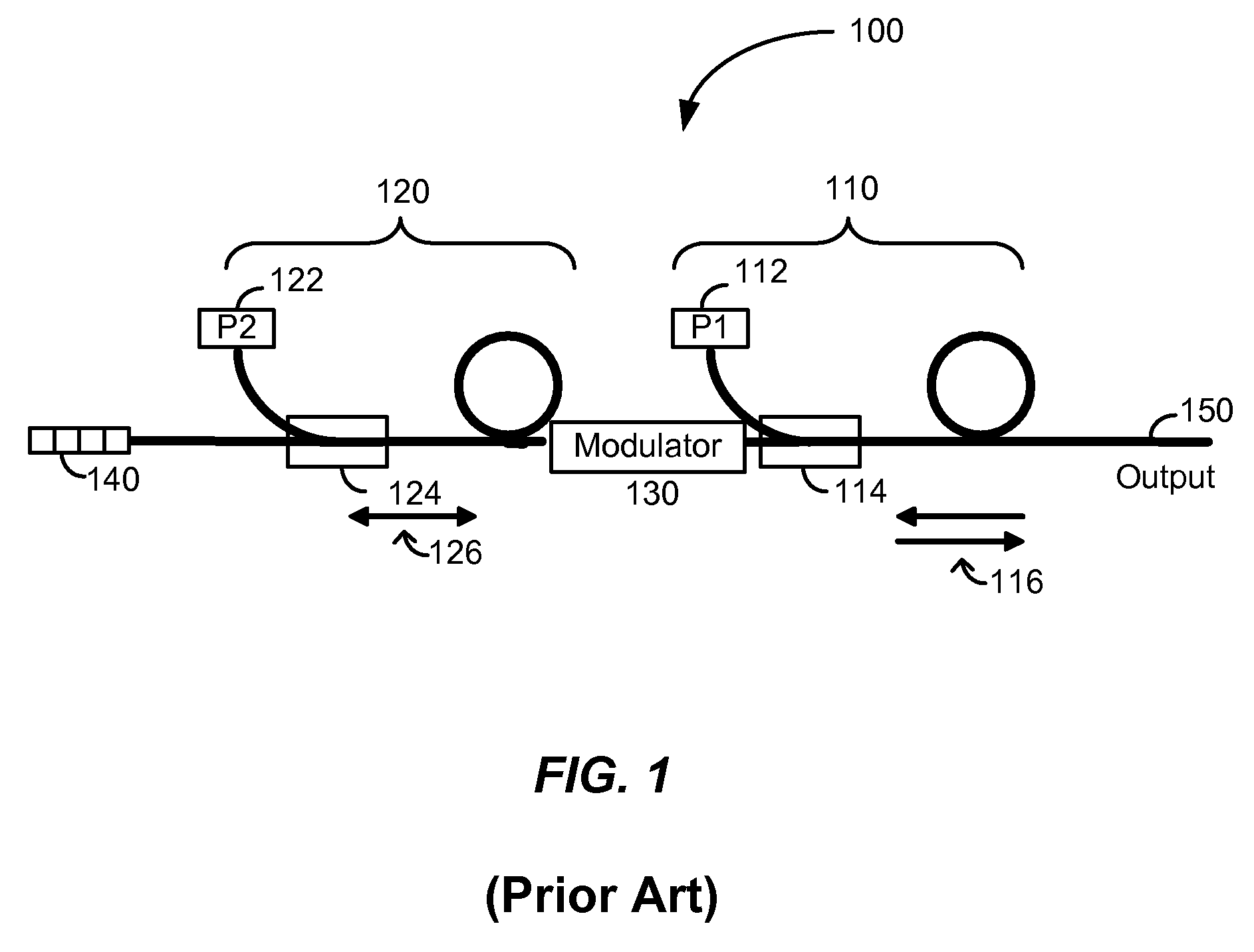
[0016]FIG. 1 is a simplified schematic illustration of a conventional low-coherence optical source. Optical source 100 includes a first optical amplifier 110, an amplitude modulator 130, a second optical amplifier 120, and a grating reflector 140. The first optical amplifier produces a continuous stream of amplified spontaneous emission (ASE), which emerges from both ends of the a...


PUM

PropertyMeasurementUnit
peak reflectanceaaaaaaaaaa
core diameteraaaaaaaaaa

Abstract

A high power pulsed optical source includes a multi-port optical circulator and a seed source coupled to a first port of the multi-port optical circulator. The seed source is adapted to provide amplified spontaneous emission. The high power pulsed optical source also includes a first reflective device coupled to a second port of the multi-port optical circulator and a first double-pass optical amplifier coupled at a first end to a third port of the multi-port optical circulator and coupled at a second end to an amplitude modulator. The high power pulsed optical source also includes a second reflective device coupled to the amplitude modulator and an output port coupled to a fourth port of the multi-port optical circulator.

Description

CROSS-REFERENCES TO RELATED APPLICATIONS[0001]The present application claims benefit under 35 U.S.C. § 119(e) of U.S. Provisional Patent Application No. 60 / 793,494, filed Apr. 19, 2006, which is incorporated herein by reference in its entirety.BACKGROUND OF THE INVENTION[0002]The present invention relates generally to the field of tunable light sources. More particularly, the present invention relates to a method and apparatus for providing high power pulsed optical sources useful for industrial applications such as trimming, marking, cutting, and welding. Merely by way of example, the invention has been applied to a light source with real-time tunable characteristics including pulse width, peak power, repetition rate, and pulse shape. However, the present invention has broader applicability and can be applied to other optical sources.[0003]Pulsed laser sources, such as Nd:YAG lasers have been used to perform laser-based material processing for applications such as marking, engravin...

Claims


Application Information

Patent Timeline
Patent Type & Authority Applications(United States)
IPC IPC(8): H01S3/10H01S3/091H01S3/092
CPCB23K26/0626B23K26/20B23K26/38H01S3/005H01S3/0057H01S3/2333H01S3/0085H01S3/06758H01S3/09415H01S3/1618H01S3/0078B23K26/21
Inventor MURISON, RICHARDPANARELLO, TULLIOREID, BENOITBOULA-PICARD, REYNALD
Owner ELECTRO SCI IND INC
Why Eureka
Try Eureka