Method and system for a pulsed laser source emitting shaped optical waveforms

a laser source and optical waveform technology, applied in the field of tunable laser sources, can solve the problems of difficult to achieve a range of variable pulse characteristics, inability to vary laser pulses in general field without compromising laser performance, etc., to achieve optimal pulse profile, optimize pulse profile, and maximize energy extraction efficiency in the laser system

Inactive Publication Date: 2009-03-12
ELECTRO SCI IND INC
View PDF8 Cites 29 Cited by
  • Summary
  • Abstract
  • Description
  • Claims
  • Application Information

AI Technical Summary

Benefits of technology

[0011]Numerous benefits are achieved using the present invention over conventional techniques. For example, in an embodiment according to the present invention, high power, pulsed lasers suitable for laser processing are provided that utilize a compact architecture that is inexpensive in comparison to lasers with comparable performance characteristics. Moreover, in embodiments of the present invention, short pulses are generated with pulse characteristics that are tunable in real-time while maintaining pulse-to-pulse stability. Furthermore, in an embodiment according to the present invention, optical pulses can be shaped to optimize the pulse profile for the particular application, or to maximize energy extraction efficiency in the laser system. Depending upon the embodiment, one or more of these benefits may exist. These and other benefits have been described throughout the present specification and more particularly below. Various additional objects, features and advantages of the present invention can be more fully appreciated with reference to the detailed description and accompanying drawings that follow.

Problems solved by technology

As such, such laser pulses cannot generally be varied in the field without compromising the laser performance.
Using such lasers, it is generally difficult to achieve a range of variable pulse characteristics.

Method used


Image

  • Method and system for a pulsed laser source emitting shaped optical waveforms
  • Method and system for a pulsed laser source emitting shaped optical waveforms
  • Method and system for a pulsed laser source emitting shaped optical waveforms

Examples


Embodiment Construction

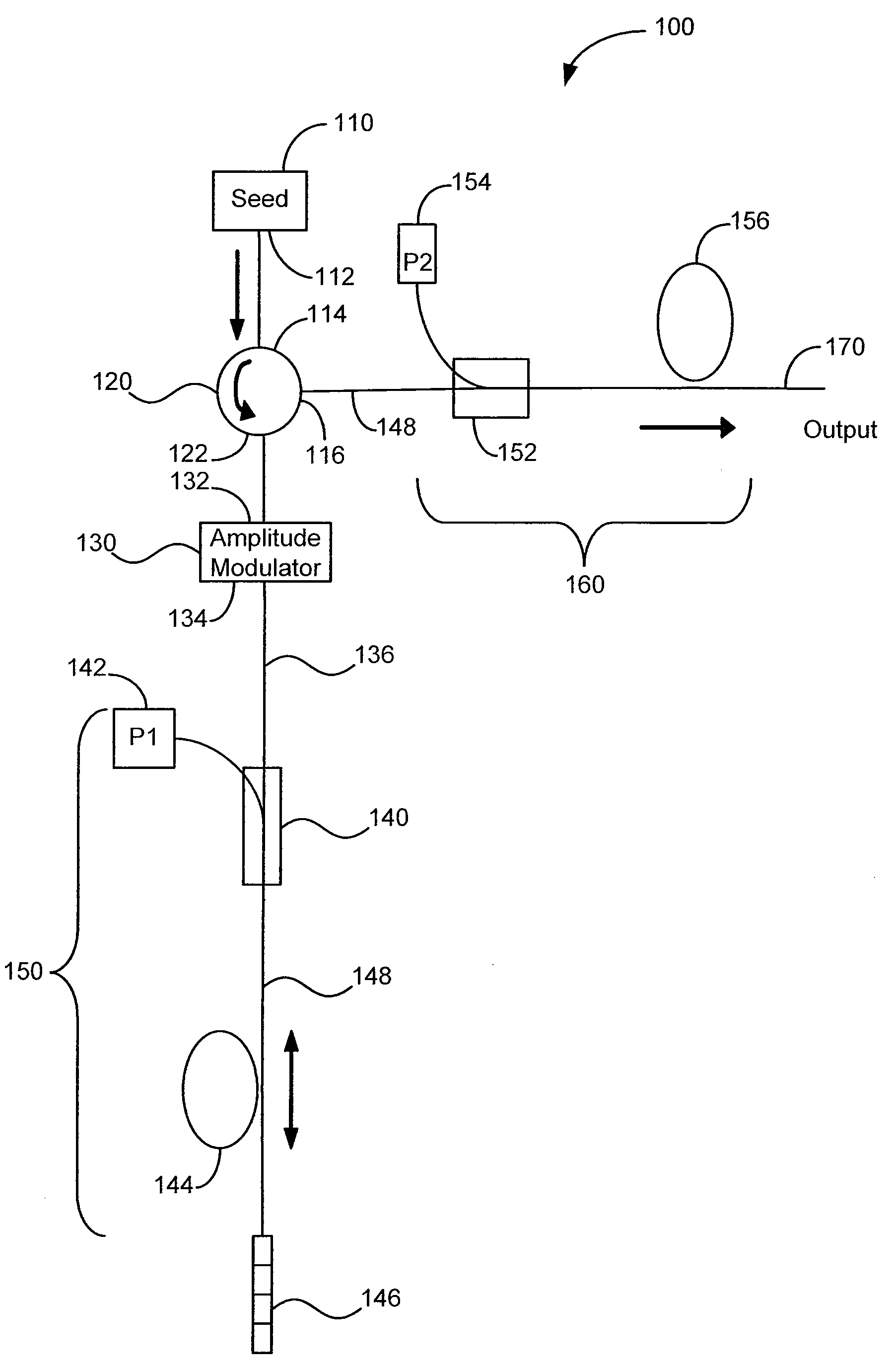
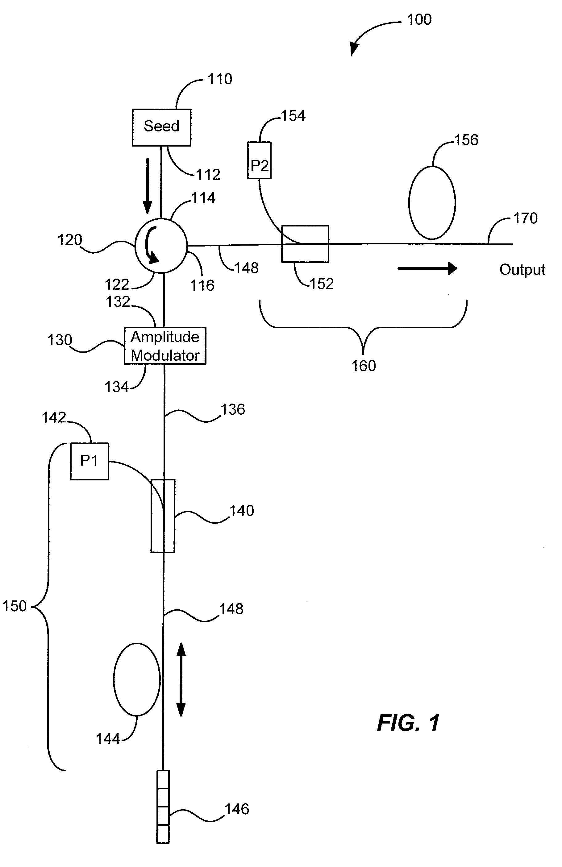
[0025]FIG. 1 is a simplified schematic illustration of a high power pulsed laser with tunable pulse characteristics using optical fiber amplifiers according to an embodiment of the present invention. High power pulsed laser 100 includes a seed source 110 that generates a seed signal that is injected into a first port 114 of an optical circulator 120. According to an embodiment of the present invention, the optical seed signal is generated by using a seed source 110 that is a continuous wave (CW) semiconductor laser. In a particular embodiment, the CW semiconductor laser is a fiber Bragg grating (FBG) stabilized semiconductor diode laser operating at a wavelength of 1032 nm with an output power of 20 mW. In another particular embodiment, the CW semiconductor laser is an external cavity semiconductor diode laser operating at a wavelength of 1064 nm with an output power of 100 mW. In alternative embodiments, the seed signal is generated by a compact solid-state laser or a fiber laser. ...


PUM

PropertyMeasurementUnit
electrical bandwidthaaaaaaaaaa
wavelengthaaaaaaaaaa
output poweraaaaaaaaaa

Abstract

A laser system for processing a workpiece includes a tunable pulsed laser source having an output comprising a set of optical pulses. The tunable pulsed laser source includes a seed source, an optical circulator having a first port coupled to the seed source, a second port, and a third port, a modulator driver, and an amplitude modulator coupled to the modulator driver. The tunable pulsed laser source also includes a first optical amplifier characterized by an input end and a reflective end and a second optical amplifier coupled to the third port of the optical circulator. The laser system also includes a controller configured to adjust laser parameters of the tunable pulsed laser source, a supporting member configured to support the workpiece, and an optical system configured to adjust laser beams from the tunable pulsed laser source and direct them towards the workpiece.

Description

CROSS-REFERENCES TO RELATED APPLICATIONS[0001]This application is a continuation-in-part of and claims the benefit of co-pending, commonly assigned U.S. patent application Ser. No. 11 / 862,935, filed Sep. 27, 2007, entitled “Method And System For A Pulsed Laser Source Emitting Shaped Optical Waveforms,” which claims the benefit under 35 U.S.C. § 119(e) of U.S. Provisional Patent Application No. 60 / 848,077, filed Sep. 29, 2006, entitled “Method And System For A Pulsed Laser Source Emitting Shaped Optical Waveforms.” The entire disclosures of the above-referenced patent applications are herein incorporated by reference for all purposes.BACKGROUND OF THE INVENTION[0002]The present invention relates generally to the field of tunable laser sources. More particularly, the present invention relates to a method and apparatus for providing high power pulsed laser sources useful for industrial applications such as trimming, marking, cutting, and welding. Merely by way of example, the invention...

Claims


Application Information

Patent Timeline
Patent Type & Authority Applications(United States)
IPC IPC(8): H01S3/10
CPCB23K26/063H01S3/005H01S3/0085H01S3/06758H01S3/0912H01S3/2333H01S3/10015H01S3/10023H01S3/10069H01S3/1618H01S3/09415B23K26/0622H01S3/1001H01S3/1003
Inventor MURISON, RICHARDPANARELLO, TULLIOREID, BENOITBOULA-PICARD, REYNALD
Owner ELECTRO SCI IND INC
Why Eureka
Try Eureka