Cryogenic vacuum RF feedthrough device

a vacuum and cryogenic technology, applied in the direction of material analysis using wave/particle radiation, instruments, nuclear engineering, etc., can solve the problem of beam “missing” and achieve the effect of maintaining useful rf transmission line characteristics and high thermal conductan

Active Publication Date: 2007-10-25
JEFFERSON SCI ASSOCS LLC
View PDF9 Cites 7 Cited by
  • Summary
  • Abstract
  • Description
  • Claims
  • Application Information

AI Technical Summary

Benefits of technology

[0006] It is therefore an object of the present invention to provide a cryogenic vacuum rf feedthrough dev

Problems solved by technology

The generation of such higher order modes can interfere with the operation of the acceler

Method used


Image

  • Cryogenic vacuum RF feedthrough device
  • Cryogenic vacuum RF feedthrough device

Examples


Embodiment Construction

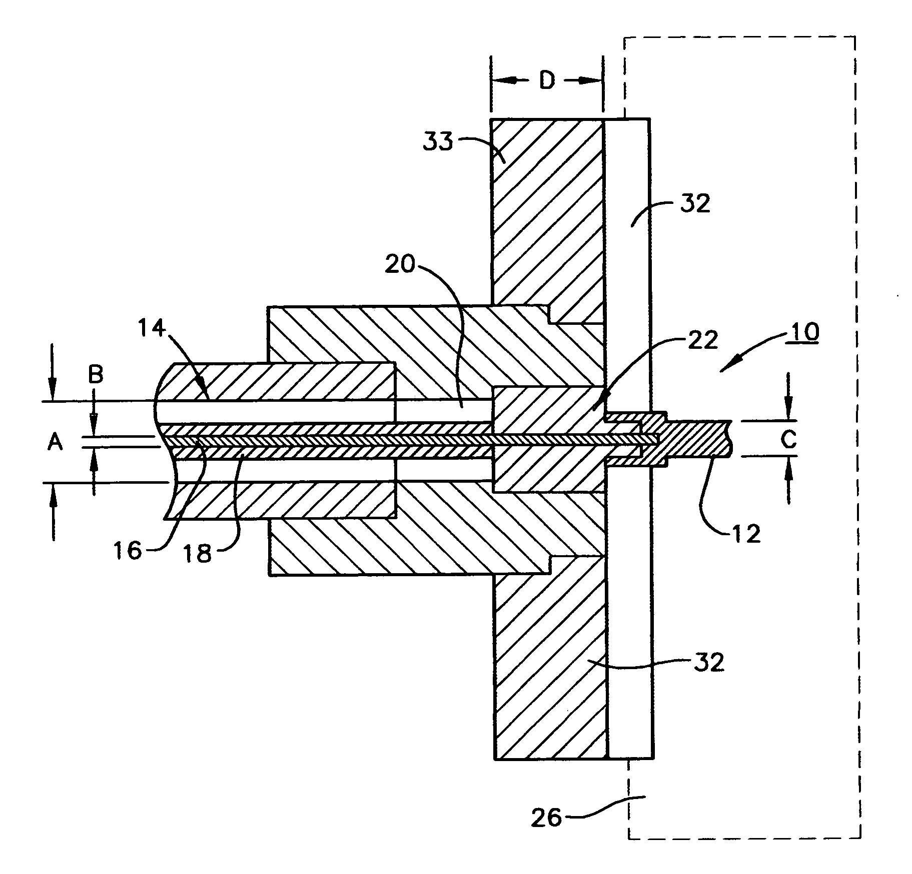
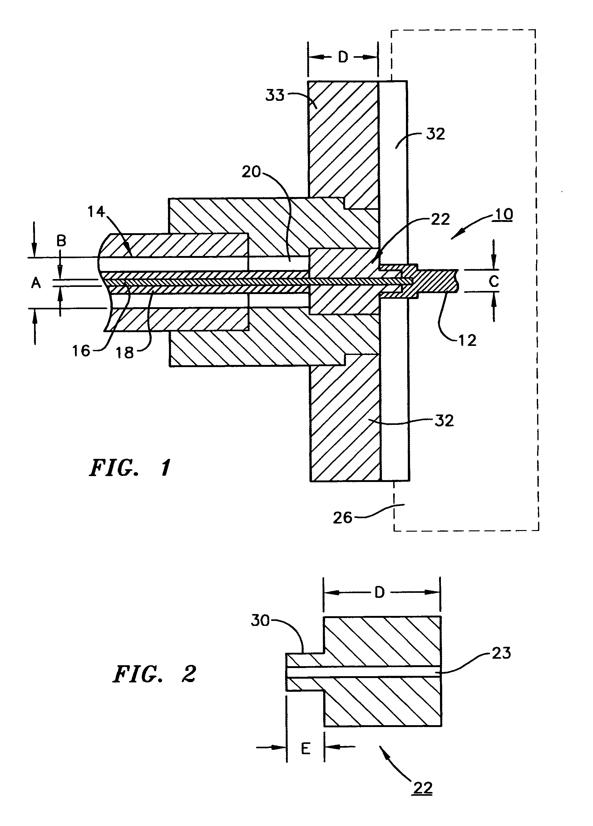
[0010] Referring now to the accompanying drawings, the cryogenic rf feedthrough device 10 of the present invention comprises a probe 12 for insertion into a particle beam traveling in the vacuum of the accelerator 26; a coaxial cable 14 comprising an inner conductor 16 and an outer conductor 18, a coaxial dielectric / insulating layer 20 surrounding the inner conductor 16, is connected to probe 12 for the transmission of higher mode rf energy from probe 12 to inner conductor 16; and 3) a high thermal conductivity stub 22 attached to the coaxial dielectric layer 20 about and in thermal contact with inner conductor 16 which high thermal conductivity stub 22 transmits heat generated in the vicinity of probe 12 efficiently and radially from the area of probe 12 and inner conductor 16 all while maintaining useful rf transmission line characteristics between the inner and outer coaxial conductors 14 and 16 respectively. As best seen in FIG. 2, stub 22 includes an aperture 23 for admission a...


PUM


Abstract

A cryogenic vacuum rf feedthrough device comprising: 1) a probe for insertion into a particle beam; 2) a coaxial cable comprising an inner conductor and an outer conductor, a dielectric/insulating layer surrounding the inner conductor, the latter being connected to the probe for the transmission of higher mode rf energy from the probe; and 3) a high thermal conductivity stub attached to the coaxial dielectric about and in thermal contact with the inner conductor which high thermal conductivity stub transmits heat generated in the vicinity of the probe efficiently and radially from the area of the probe and inner conductor all while maintaining useful rf transmission line characteristics between the inner and outer coaxial conductors.

Description

[0001] The United States of America may have certain rights to this invention under Management and Operating contract No. DE-AC05-84ER 40150 from the Department of EnergyFIELD OF THE INVENTION [0002] The present invention relates to cryogenic vacuum rf feedthrough devices and more particularly to such a device that provides optimized thermal conductivity and concomitant heat extraction. BACKGROUND OF THE INVENTION [0003] Particle accelerators utilize a fundamental rf power and frequency to accelerate the particle beam. As the accelerator operates, the beam stimulates the production of rf energy at different frequencies than those used to power the device (referred to as higher order modes). The generation of such higher order modes can interfere with the operation of the accelerator and also generate heat within the accelerator resulting in “missteering” of the beam. It is therefore desirable and necessary that such higher order rf frequencies and the heat generated thereby be extra...

Claims


Application Information

Patent Timeline
IPC IPC(8): H04B1/38H04B1/04H01Q11/12
CPCH01Q1/50
Inventor WU, GENFAPHILLIPS, HARRY LAWRENCE
Owner JEFFERSON SCI ASSOCS LLC
Why Eureka
Try Eureka