
Communication Control System

ontrol system technology, applied in the field of communication control systems, can solve the problems of insufficient compatibility of reliability and real time property when used in industrial applications, and the difficulty of providing such a communication control system, so as to prevent security attacks, avoid interruption of open communication, and high reliability

Active Publication Date: 2007-10-25
YOKOGAWA ELECTRIC CORP
View PDF2 Cites 8 Cited by
  • Summary
  • Abstract
  • Description
  • Claims
  • Application Information

AI Technical Summary

Benefits of technology

[0099] As understood from the discussion, the invention provides the following advantages:
[0107] (8) The same communication path and transmitting / receiving section are shared in the same communication station for communications that is based on an open standard protocol and critical communications. This reduces the component cost and wiring cost.

Problems solved by technology

Industrial Ethernet(registered trademark) does not currently satisfy the real time property or reliability requested in process control so that it is difficult to provide such a communication control system.
In a conventional system, it is difficult to implement open protocol communications while assuring real time property and reliability from the following circumstances: (a) Communications over a standard protocol that is based on Ethernet(registered trademark) or TCP / IP (Transmission Control Protocol / Internet Protocol) do not sufficiently satisfy the needs for real time property and reliability when used in industrial applications such a process control.
(b) Communications over a unique dedicated protocol for attaining real time property and reliability have only insufficient compatibility when connected to another system or when a network device or software widely available on the market is used.
This does not sufficiently meet the request for open protocol communications.

Method used


Image

  • Communication Control System
  • Communication Control System
  • Communication Control System

Examples


first embodiment

(1) First Embodiment

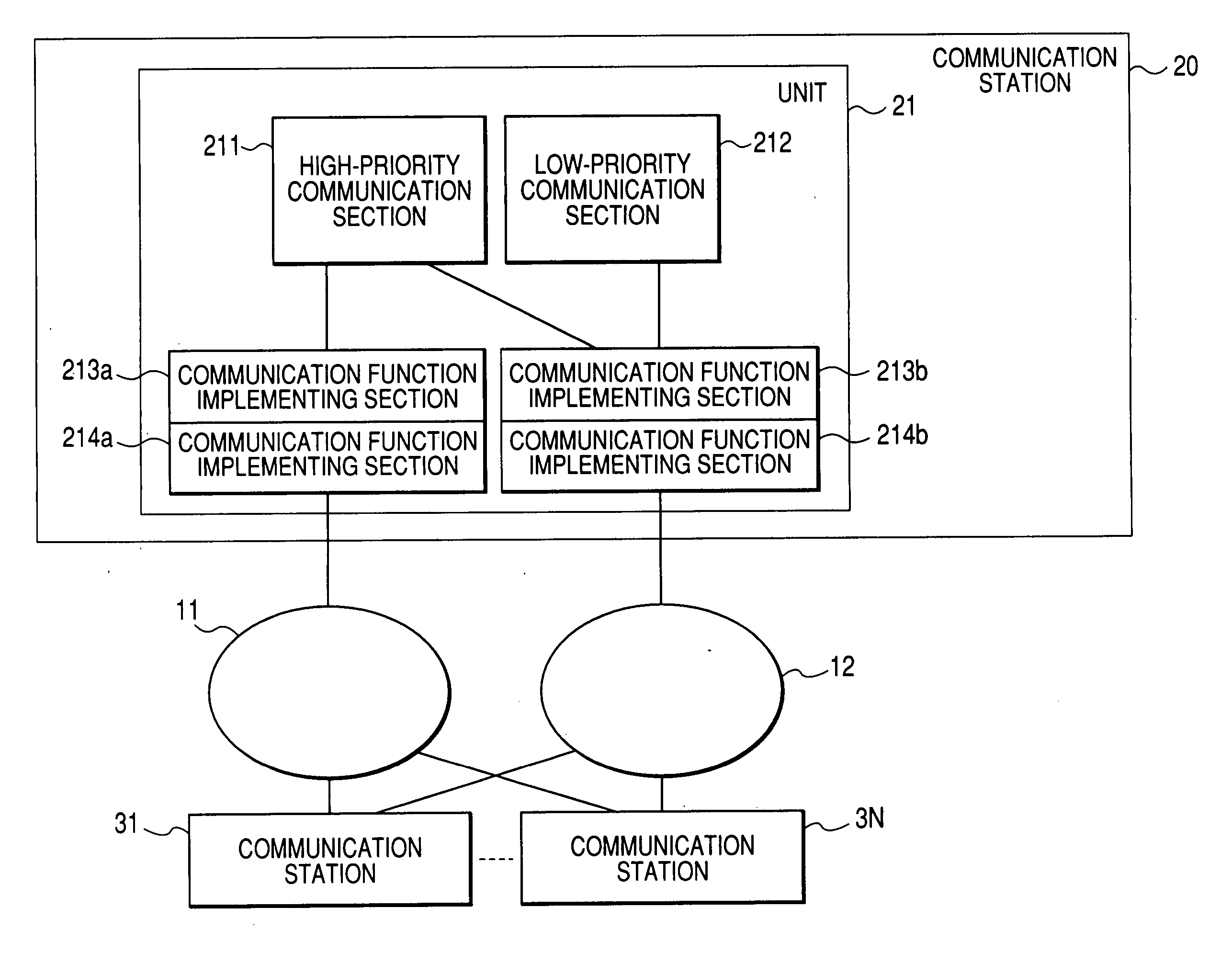
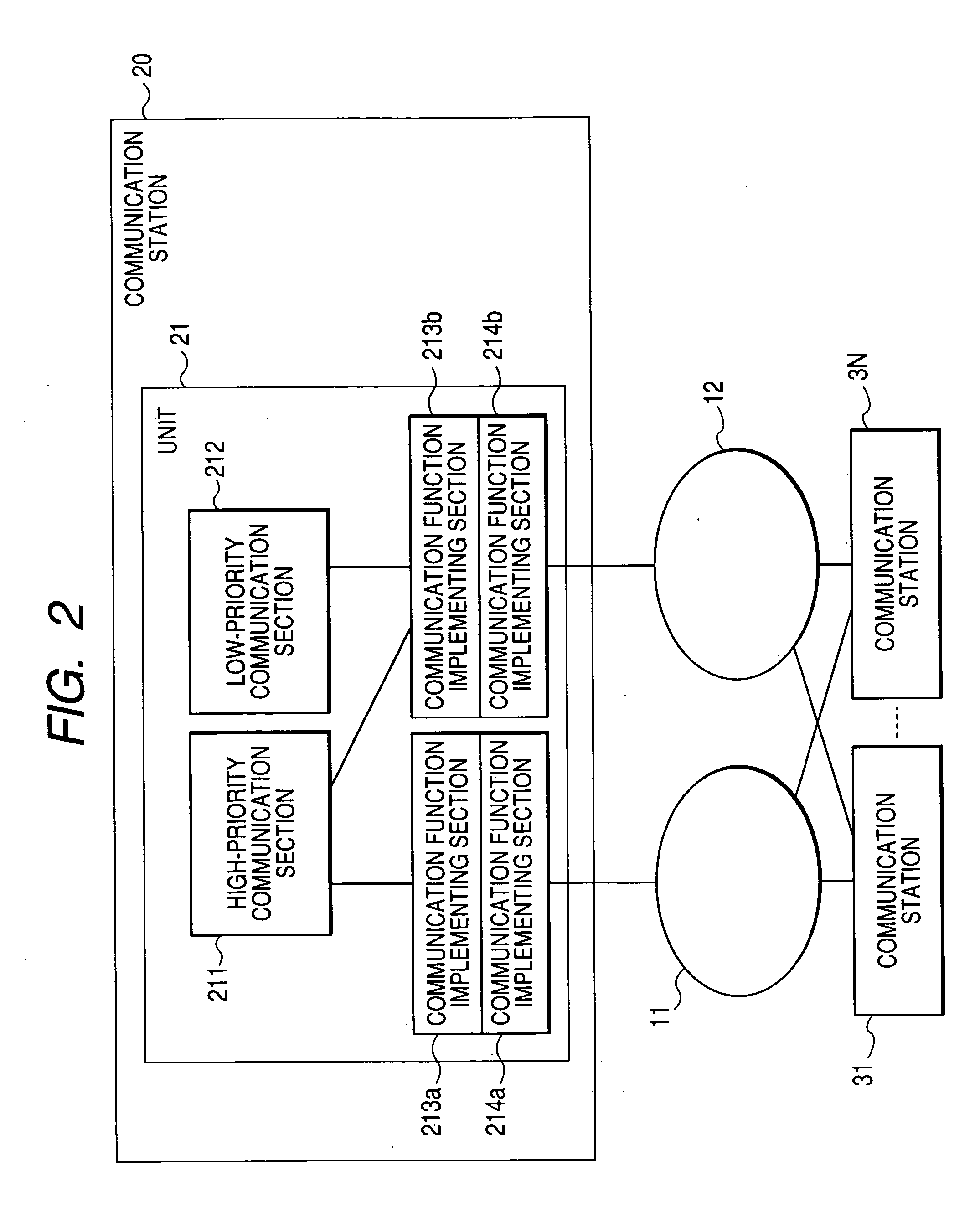
[0125]FIG. 2 is a block diagram showing an embodiment of the invention. In FIG. 2, a communication path 10 is duplicated by a main path 11 and a sub-path 12. The communication path 10 is for example the control bus of a distributed control system.

[0126] A communication station 20 and communication stations 31 to 3N are connected to the main path 11 and the sub-path 12.

[0127] The communication station 20 includes a unit 21 for performing communications. The embodiment in FIG. 1 includes a single unit.

[0128] In the unit 21, high-priority communication section 211 performs high-priority communications. Low-priority communication section 212 performs low-priority communications.

[0129] High-priority communications transfer process data, an operation amount, an alarm and the like. Low-priority communications performs image data transfer, file transfer, message transfer, and the like. High-priority communications transfer more real time data while low-priority commu...

second embodiment

(2) Second Embodiment

[0148]FIG. 4 is a block diagram of another embodiment of the invention. In FIG. 4, same components as the preceding ones are given the same signs. In this embodiment, the unit is duplicated.

[0149] A communication station 22 includes a dual unit 21a and 21b. The unit 21a includes high-priority communication section 211, low-priority communication section 212, communication function implementing section 213a, 213b, 214a, 214b. The unit 21b has the same configuration as the unit 21a. In the illustrated example, the unit 21a serves as an active 25 unit and the unit 21b serves as a standby unit.

[0150] The active unit 21a performs communications. When the active unit 21a turns faulty, the unit 21a halts communications and places itself in the standby state. The standby unit 21b switches to the active unit and takes over the communications. In this embodiment, the unit is duplicated thus enhancing the reliability of communications. The unit may be triplicated or furt...

third embodiment

(3) Third Embodiment

[0151]FIG. 5 is a block diagram of another embodiment of the invention.

[0152] In FIG. 5, a communication station 40 is connected to a main path 11 and a sub-path 12.

[0153] High-priority communication section 401 performs high-priority communications by using the main path 11.

[0154] Low-priority communication section 402 performs low-priority communications by using the sub-path 12.

[0155] Path diagnosing section 403 diagnoses the soundness of the main path 11 and the sub-path 12.

[0156] Switching section 404 switches the communication path between the high-priority communication section 401 and its distant party based on the diagnosis result of the path diagnosing section 403.

[0157] Restricting section 405 restricts communications by the low-priority communication section 402 based on the diagnosis result of the path diagnosing section 403. For example, the restricting section 405 restricts the transmission band of the low-priority communication section 402. ...


PUM


Abstract

A communication control system is provided that performs communications satisfying a request for industrial applications and a request for open protocol communications at the same time. To this end, in the invention, a high-priority communication section performing critical communications to provide real time property and reliability, and a low-priority communication section performing communications based on an open standard protocol coexist in a same communication station.

Description

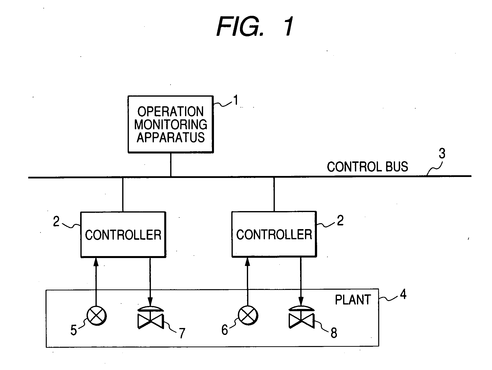
TECHNICAL FIELD [0001] The present invention relates to a communication control system used for a distributed control system or the like. BACKGROUND ART [0002] The distributed control system is used for plant operation control in a wide variety of fields such as petrochemistry, steel, paper pulp, foods, pharmaceuticals, and electric power. [0003]FIG. 1 shows an exemplary configuration of a general distributed control system. [0004] Referring to FIG. 1, an operation monitoring apparatus 1 and a controller 2 are connected to a control bus 3. The controller 2 controls a plant 4 under the monitoring of the operation monitoring apparatus 1. The operation monitoring apparatus 1 is in charge of operation and monitoring of the plant. The operation monitoring apparatus 1 displays a screen to perform control operation and monitoring. In accordance with the scale of the plant, a plurality of controllers are distributed across the plant. The operation monitoring apparatus 1 and the controller 2...

Claims


Application Information

Patent Timeline
IPC IPC(8): G05B15/02H04L12/40H04L12/28H04L29/06H04L29/08
CPCH04L12/40143H04L12/40182H04L67/322H04L45/00H04L29/06H04L67/61H04L9/40
Inventor DEMACHI, KOJIEBASHI, HIROMICHIAKABANE, KUNIHARUNAKAJIMA, TAKESHIHABAGUCHI, KENJIMURAKAMI, MASAYUKIYOKOI, TOYOAKIHONGO, TAKESHIISHII, AKINORISOGO, SADATOSHI
Owner YOKOGAWA ELECTRIC CORP
Learn More