
Optimizing Control Method and System, Overall Control Apparatus and Local Control Apparatus

Inactive Publication Date: 2007-10-25
HITACHI LTD
View PDF7 Cites 14 Cited by
  • Summary
  • Abstract
  • Description
  • Claims
  • Application Information

AI Technical Summary

Benefits of technology

[0008] In view of the problems of the prior art described above, the object of this invention is to provide an optimizing control method, an optimizing control system, an integration control apparatus and a local control apparatus capable of optimizing a plurality of control parameters and reducing the time and labor required to construct the control system.
[0013] According to this invention, the integration control apparatus and the plurality of the local control apparatuses are connected to each other through a plurality of control information standardization interfaces corresponding to the respective local control apparatuses. The integration control apparatus, therefore, can obtain the physical status amounts of the local apparatuses output from various local control apparatuses in the form of a standard physical status amount expressed by the standard physical quantities regardless of the difference among the local control apparatuses. Also, the constraints and the evaluation function for each local control apparatus can be expressed by the corresponding standard physical quantity, and therefore, the integration control apparatus can easily generate an integrated constraints and an integration evaluation function combining the constraints and the evaluation functions of the local control apparatuses. As a result, the control goal values for the plurality of the local control apparatuses can be easily calculated as an optical setpoint indicated by the standard physical quantity.
[0014] Each control information standardization interface has stored therein the constraints and the evaluation function indicated by the standard physical quantity for controlling the local apparatus controlled by the local control apparatus. Even in the case where a new local control apparatus is added to the integration control apparatus, therefore, the integration control apparatus can easily generate the integrated constraints and the integration evaluation function by acquiring the constraints and the evaluation function from the control information standardization interface. Also, even in the case where the local control apparatus connected to the integration control apparatus is disconnected, the constraints and the evaluation function for the local control apparatus can be easily deleted from the integrated constraints and the integration evaluation function.
[0015] Specifically, according to this invention, the local control apparatus can be easily added to or deleted from the integration control apparatus. In other words, as long as the control information standardization interface is prepared for the local control apparatus, the optimizing control system can be easily constructed using the particular local control apparatus. As a result, an optimizing control system capable of optimizing a plurality of control parameters can easily constructed, and the time and labor required for the construction thereof can be reduced.
[0016] According to this invention, the optimizing control system capable of optimizing a plurality of control parameters can be easily constructed, and the time and labor required for the construction can be reduced.

Problems solved by technology

The model control scheme, however, requires the development of a particular model for each control system, and with the increased scale and the resulting complication of the control system, requires a great amount of time and labor for development.
In the control system disclosed in Patent Document 1, however, the model control scheme is used, and therefore, the problem of the prior art that a great amount of time and labor is required for model development of the control system has yet to be solved.
Taking the current global environment problem into consideration, the development of various energy-saving systems is expected to come to be required in the future, and the aforementioned problem of the model control scheme, however, hampers the development of the energy-saving systems.
Especially, in the control system for ordinary homes and automotive vehicles which are short in product life and whose configuration often undergoes a change, the development and application of the optimizing control system by the model control scheme cannot be considered to have a practical value.

Method used


Image

  • Optimizing Control Method and System, Overall Control Apparatus and Local Control Apparatus
  • Optimizing Control Method and System, Overall Control Apparatus and Local Control Apparatus
  • Optimizing Control Method and System, Overall Control Apparatus and Local Control Apparatus

Examples


first embodiment

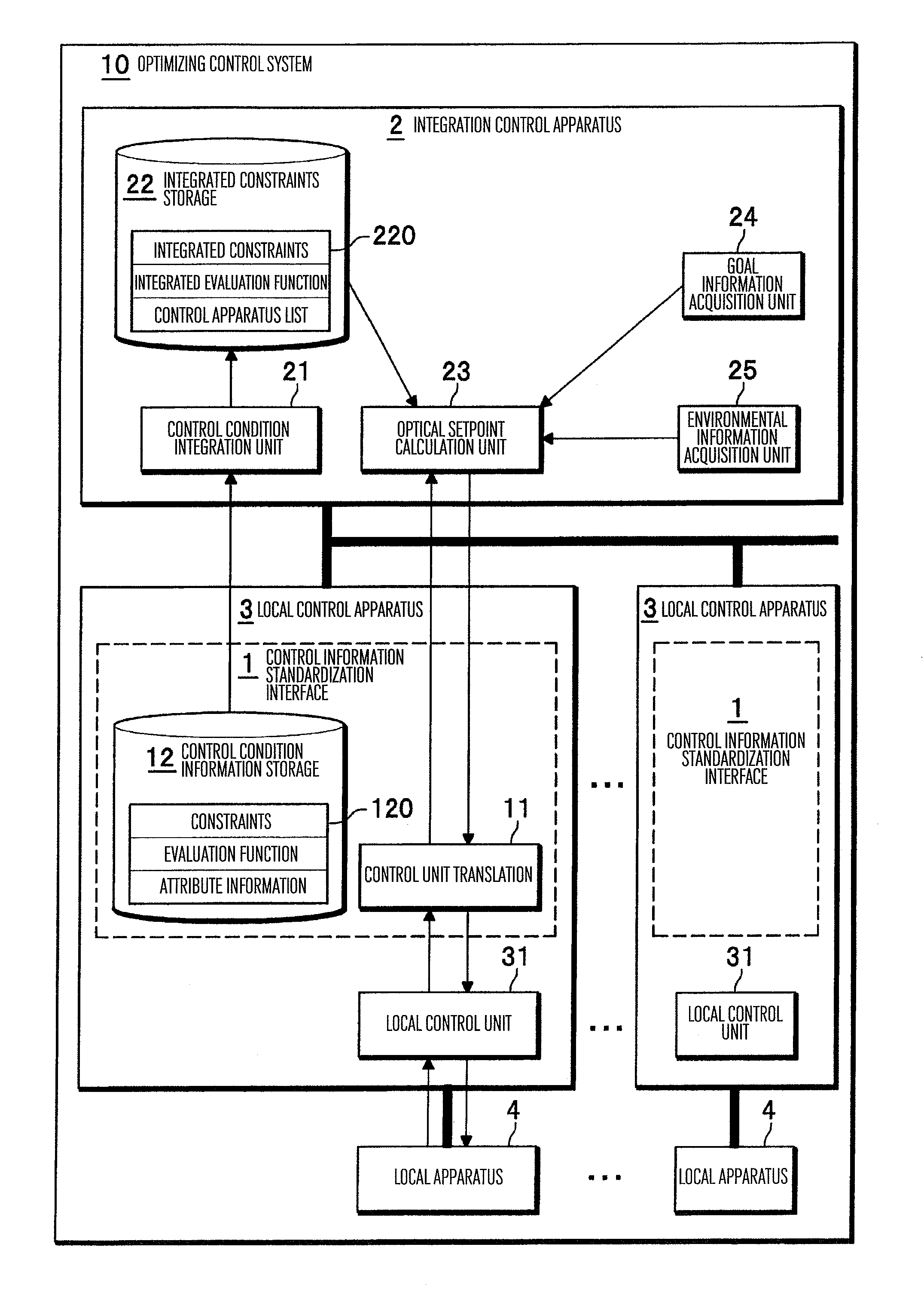
[0028]FIG. 1 is a diagram showing an example of the configuration of the optimizing control system according to a first embodiment of the invention. As shown in FIG. 1, the optimizing control system 10 according to this embodiment includes a plurality of local control apparatuses each connected to a local apparatus 4 for controlling the particular local apparatus 4 and an integration control apparatus 2 connected to a plurality of the local control apparatuses 2 to control the plurality of the local control apparatuses 3 in integration fashion.

[0029] In FIG. 1, each local control apparatus 3 includes a local control apparatus 31 for controlling the local apparatus 4 individually and a control information standardization interface 1 arranged between a local control unit 31 and the integration control apparatus 2 for standardizing the control information transmitted and received between the local control unit 31 and the integration control apparatus 2. Also, each control information ...

second embodiment

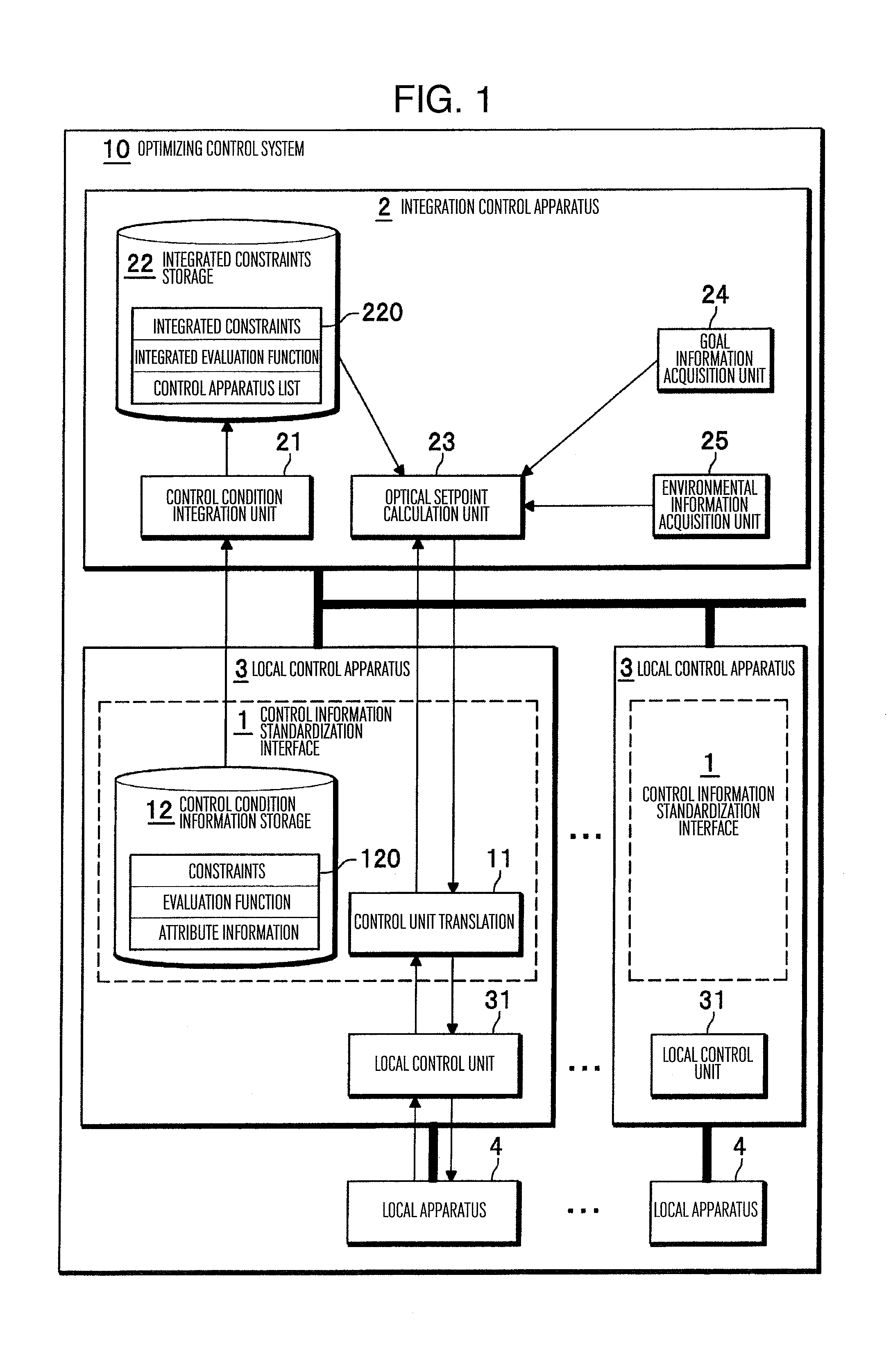
[0062]FIG. 2 is a diagram showing an example of the configuration of the optimizing control system according to a second embodiment of the invention. As shown in FIG. 2, the optimizing control system 10a according to the second embodiment includes local control apparatuses 3a each connected to a local apparatus 4 for controlling the same local apparatus 4, and an integration control apparatus 2a connected to a plurality of the local control apparatuses 3a to control the plurality of the local control apparatuses 3a in integration fashion. In FIG. 2, the component elements having the same functions as those in FIG. 1 are designated by the same reference numerals, respectively.

[0063] In the optimizing control system 10a according to the second embodiment is different from the optimizing control system 10 according to the first embodiment (FIG. 1) in that in the second embodiment, each control information standardization interface 1 is included not in the local control apparatus 3a bu...

third embodiment

[0069]FIG. 3 is a diagram showing an example of the configuration of the optimizing control system according to a third embodiment of the invention. As shown in FIG. 3, the optimizing control system 10b according to the third embodiment includes a plurality of local control apparatuses 3b connected to the local apparatuses 4 to control the local apparatuses 4, and an integration control apparatus 2b connected to a plurality of the local control apparatuses 3b to control the plurality of the local control apparatuses 3b in integration fashion. In FIG. 3, the component elements having the same functions as those in FIG. 1 are designated by the same reference numerals, respectively.

[0070] The optimizing control system 10b according to the third embodiment is different from the optimizing control system 10 (FIG. 1) according to the first embodiment in that in the optimizing control system 10b, the physical quantity converter 11 is included not in each local control apparatus 3b but in ...


PUM


Abstract

An optimizing control system includes at least a local control unit for controlling at least a control apparatus, an integration control apparatus for controlling a plurality of the local control units in integration fashion, and at least a control information standardization interface arranged between the local control unit and the integration control apparatus for standardizing the control information transmitted and received between the local control unit 31 and the integration control apparatus. The control information standardization interface includes a control condition information storage unit for storing the constraints, the evaluation function and the attribute information expressed by a predetermined standard physical quantity for controlling the local apparatus, and a physical quantity converter for converting the local physical status amount acquired from the local apparatus into a standard physical status amount and converting the optical setpoint calculated by the integration control apparatus into a local control goal value.

Description

BACKGROUND OF THE INVENTION [0001] This invention relates to an optimizing control method, an optimizing control system, an integration control apparatus and a local control apparatus for optimally controlling a plurality of apparatuses for the same purpose in integration fashion. [0002] It is now of an urgent necessity to tackle the problem of the reduction in CO2 emission to prevent the global warming over the whole world. In view of this, various technological development efforts are going on to improve the energy use efficiency by reducing the wasteful energy consumption in all fields including factories (including plants), office buildings, public facilities / buildings, automotive vehicles and homes in general. In automotive vehicles and railway vehicles, for example, the reuse of energy has been made possible by use of a regeneration brake and the use of clean energy such as the solar power is being developed in ordinary homes. [0003] In the case where a multiplicity of energy-...

Claims


Application Information

Patent Timeline
IPC IPC(8): G05B13/02G06F19/00G06Q10/04
CPCG05B13/024G05B15/02G06Q50/06G06Q10/04
Inventor ARITA, HIROSHINAKATSUKA, YASUHIRO
Owner HITACHI LTD
Features
  • Generate Ideas
  • Intellectual Property
  • Life Sciences
  • Materials
  • Tech Scout
  • Unparalleled Data Quality
  • Higher Quality Content
  • 60% Fewer Hallucinations
Learn More