Reduced Complexity Frequency Domain Equalization of Multiple Input Multiple Output Channels

a frequency domain and equalization technology, applied in the field of equalization of can solve the problem that the proposal is not suited to a frequency-selective transmission channel, and achieve the effect of reducing computational complexity and improving equalization performan

Inactive Publication Date: 2007-11-01
WSOU INVESTMENTS LLC
View PDF28 Cites 79 Cited by
  • Summary
  • Abstract
  • Description
  • Claims
  • Application Information

AI Technical Summary

Benefits of technology

[0030] Using said second-type equalization filter that is based on said first-type equalization filter can be considered as the fundamental step to reduce the computational complexity encountered in the equalization of frequency-selective transmission channels. A first-type equalization filter computed from a representation of at least one sub-carrier channels can be used to equalize all sub-carrier channels in said set of sub-carrier channels (if all second-type equalization filters used for the remaining sub-carrier channels in said set equal said first-type equalization filter), so that instead of having to compute equalization filters for all sub-carrier channels in said set, only one first-type equalization filter has to be computed. Alternatively, second-type equalization filters for some or all sub-carriers may be gained via inter- or extrapolation of only a few first-type respective equalization filters that are computed for two or more respective sets of sub-carrier channels. The present invention thus effectively reduces the computationally most expensive part of the equalization, namely the computation of equalization filters for each sub-carrier channel. The performance of this reduced-complexity equalization scheme as proposed by the present invention may depend on the technique how said representation of said at least one sub-carrier channel is determined, on the size of the sets of sub-carriers, on the way how the second-type equalization filters are derived from the first-type equalization filters, and on the differences between the sub-carrier channels.
[0075] According to a method of the present invention, said feed-back is differential. Then only differences between quantized or non-quantized information on said equalization filters may be fed back, which, in comparison to absolute feedback, may reduce the amount of feedback data.

Problems solved by technology

Furthermore, all hardware characteristics effecting the signal during the transmission from the transmitter baseband to the receiver baseband are lumped to the space-time MIMO channel matrix as well, as for instance pulse shape filters, correlations due to antenna coupling or calibration errors, phase shifts due to non-ideal mixing or lack of transmitter-receiver clock synchronism, or delays due to filtering times.
With the N sub-carrier channels H(n) being roughly equal only for frequency-flat transmission channels, this proposal is however not suited for frequency-selective transmission channels, where at least some of the N sub-carrier channels H(n) are substantially different from each other.

Method used


Image

  • Reduced Complexity Frequency Domain Equalization of Multiple Input Multiple Output Channels
  • Reduced Complexity Frequency Domain Equalization of Multiple Input Multiple Output Channels
  • Reduced Complexity Frequency Domain Equalization of Multiple Input Multiple Output Channels

Examples


first embodiment

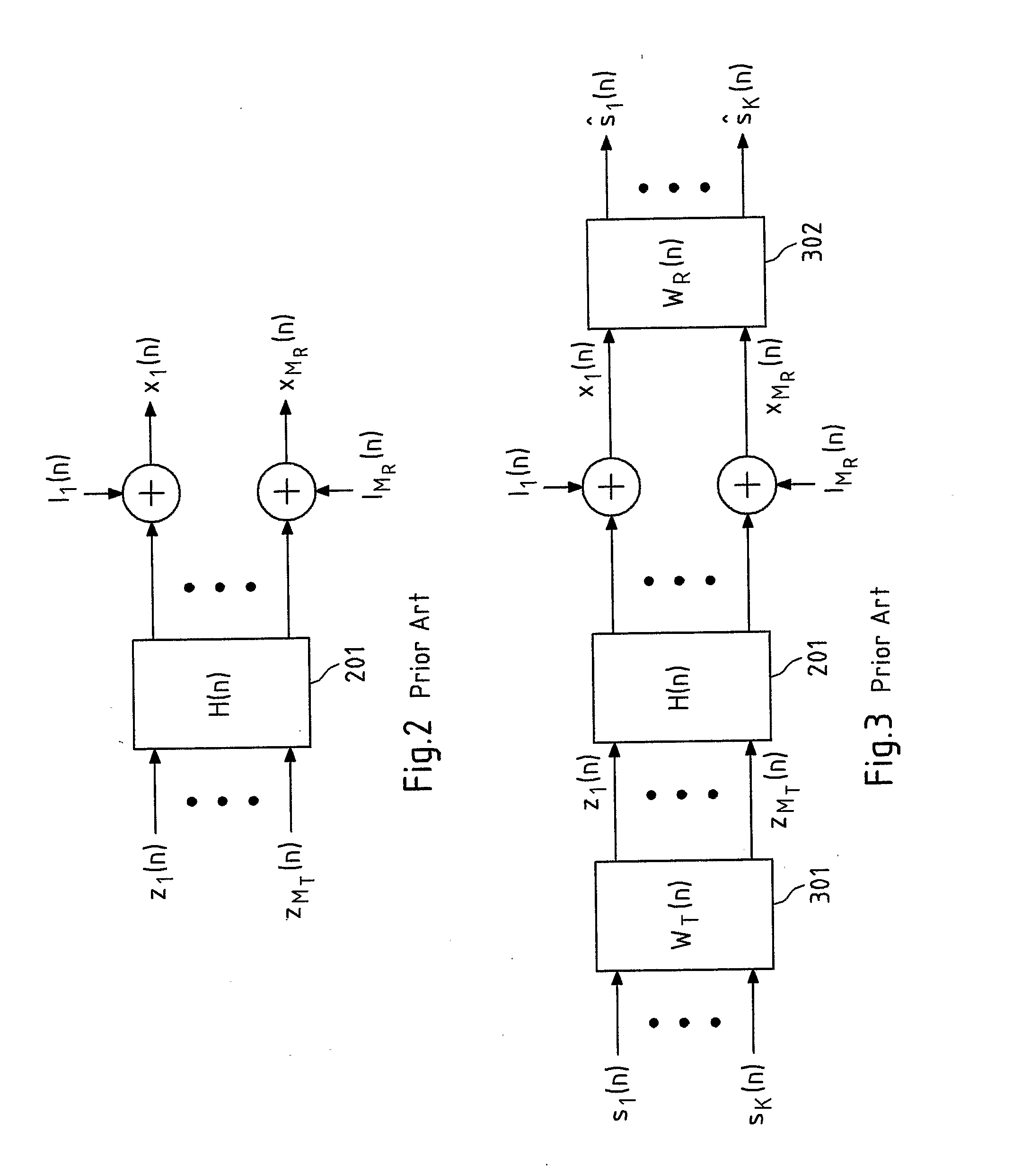
[0113]FIG. 5 schematically depicts the present invention. In particular, FIG. 5 depicts the pre- and / or post-equalization of N decoupled sub-carrier channels H(n) 201 with corresponding pre-equalization filters WT(n) 301 and post-equalization filters WR(n) 302. It is readily understood that the cases in which only pre-equalization or only post-equalization is performed are included in this schematic representation as well, for instance, by appropriately setting the post- or pre-equalization filters equal to an identity matrix, respectively. The pre- and / or post-equalization allows for a reconstruction of the symbols sk(n) transmitted over each sub-carrier channel H(n), yielding reconstructed symbols ŝk(n).

[0114] In FIG. 5, the formation of a set 501 of sub-carrier channels H(n) 201 comprising {tilde over (B)} sub-carrier channels is depicted in dashed lines. The size {tilde over (B)} of said set 501 may for instance be deduced from an estimation or measurement of the channel coheren...

second embodiment

[0117] In the present invention according to FIG. 6, a set 501 of sub-carrier channels 201 is formed as in FIG. 5, and for said set of sub-carrier channels, a first-type equalization filter is determined based on either a single (e.g., a first or center) or an averaged sub-carrier channel (e.g. averaged over all sub-carrier channels of a set 501 of sub-carrier channels). As in the embodiment of FIG. 5, K−1 sets 501 of {tilde over (B)} sub-carrier channels each with one respective determined first-type equalization filter WT,b and / or WR,b with b=1, . . . ,N / {tilde over (B)} are formed. However, the second-type equalization filters in each of said sets 501 are not derived as identical equalization filters from said respective first-type equalization filters, but are obtained via interpolation and / or extrapolation, as is indicated by the notation WT,b=f⁡(n;B~;N;WT,1,…⁢ ,WT,NB_)

(for WT,b=f(n;{tilde over (B)};N;WT,1, . . . ,WT,N / B)

(for WR,b correspondingly), i.e. each equalization fi...


PUM


Abstract

A method for equalizing a frequency-selective transmission channel (103) with N inputs and MR outputs is shown, the transmission channel representable in a transformation domain based on N orthogonal sub-carriers, and wherein the transmission characteristics from the MT inputs to the MR outputs for each of the N respective orthogonal sub-carriers are represented by N respective sub-carrier channels (201), the method using (904) equalization filters (301, 302) for at least two of the N sub-carrier channels, wherein at least one set (501) of sub-carrier channels comprising at least two of the N sub-carrier channels is formed (901), wherein for at least one sub-carrier channel, a first-type equalization filter is used that is determined (902) based on a representation of at least one sub-carrier channel, and wherein for at least one sub-carrier channel, a second-type equalization filter is used that is derived (903) at least partially from the first-type equalization filter.

Description

FIELD OF THE INVENTION [0001] This invention relates to a method, a device, a system, a computer program and a computer program product for equalizing a frequency-selective transmission channel with MT inputs and MR outputs. BACKGROUND OF THE INVENTION [0002] In the development of radio communication systems of the third (3G) and fourth (4G) generation, particular emphasis is put on the exploitation of the spatial domain of the transmission medium in order to increase the spectral efficiency (measured in bit / s / Hz) of these systems. To exploit the spatial domain, at least two antenna elements have to be provided at a transmitter and / or receiver of a radio communication system, for instance in the shape of an antenna array with at least two antenna elements. By base-band manipulation of the signals fed to these antenna elements or received from these antenna elements, it becomes then possible to transmit and / or receive signals in a spatially selective fashion, for instance to place a ...

Claims


Application Information

Patent Timeline
Patent Type & Authority Applications(United States)
IPC IPC(8): H04L1/06H04L25/03
CPCH04L1/06H04L25/0204H04L25/0244H04L2025/03522H04L25/03159H04L2025/03375H04L25/0248
Inventor TIRKKONEN, OLAVKOKKONEN, MIKKO
Owner WSOU INVESTMENTS LLC
Why Eureka
Try Eureka