
Transmitting multi-row chain

a multi-row chain and chain technology, applied in the direction of driving chains, chain elements, belts/chains/gearrings, etc., can solve the problems of increased slide resistance, troublesome close fitting operation, and excessive assembly effort, so as to enhance tensile strength and elastic modulus, high precision, and the like. the effect of disconnection and connection

Inactive Publication Date: 2007-11-01
TAMIYA ATSUHIRO
View PDF6 Cites 11 Cited by
  • Summary
  • Abstract
  • Description
  • Claims
  • Application Information

AI Technical Summary

Benefits of technology

[0005]Further, since in the above-mentioned multi-row chain the intermediate plate has the same outer appearance as each of the inner plate and the outer plate, there was a problem in that the intermediate plate travels in an excessive frictional contact with the inner and outer plates as well as other members such as a chain guide and the like so that its slide resistance is increased and the operating noise is also increased.
[0006]Accordingly, the object of the present invention is to solve the above-mentioned prior art problems and to provide a transmitting multi-row chain in which the chain strength is high, the chain is lightweight, and the disassembly and assembly operation of the chain such as disconnecting and connecting of the chain and the like is simple.
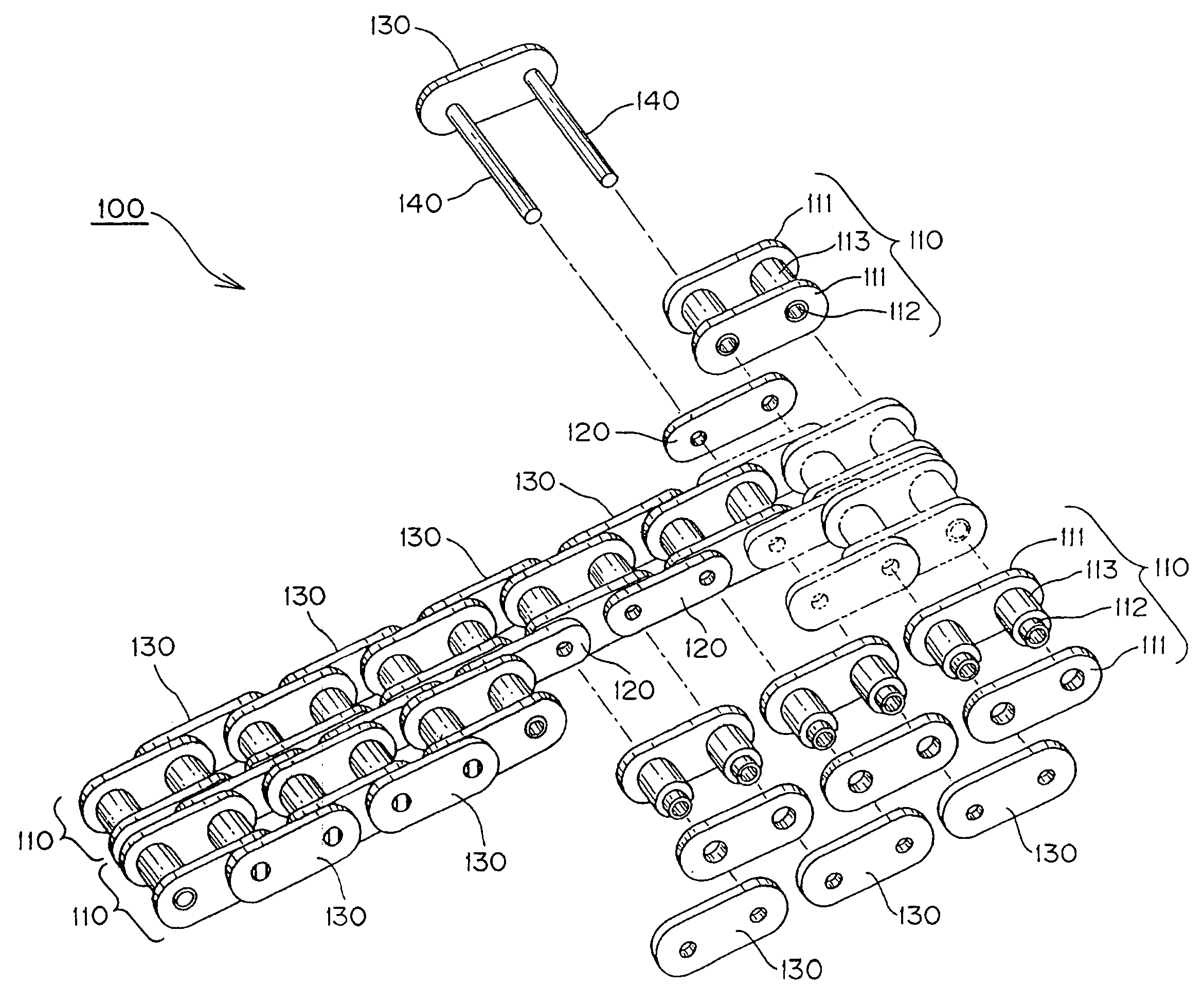
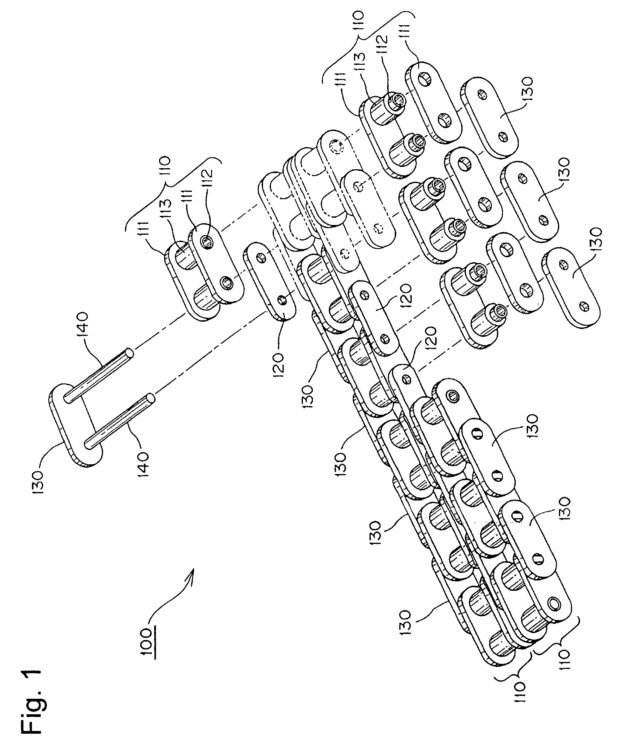
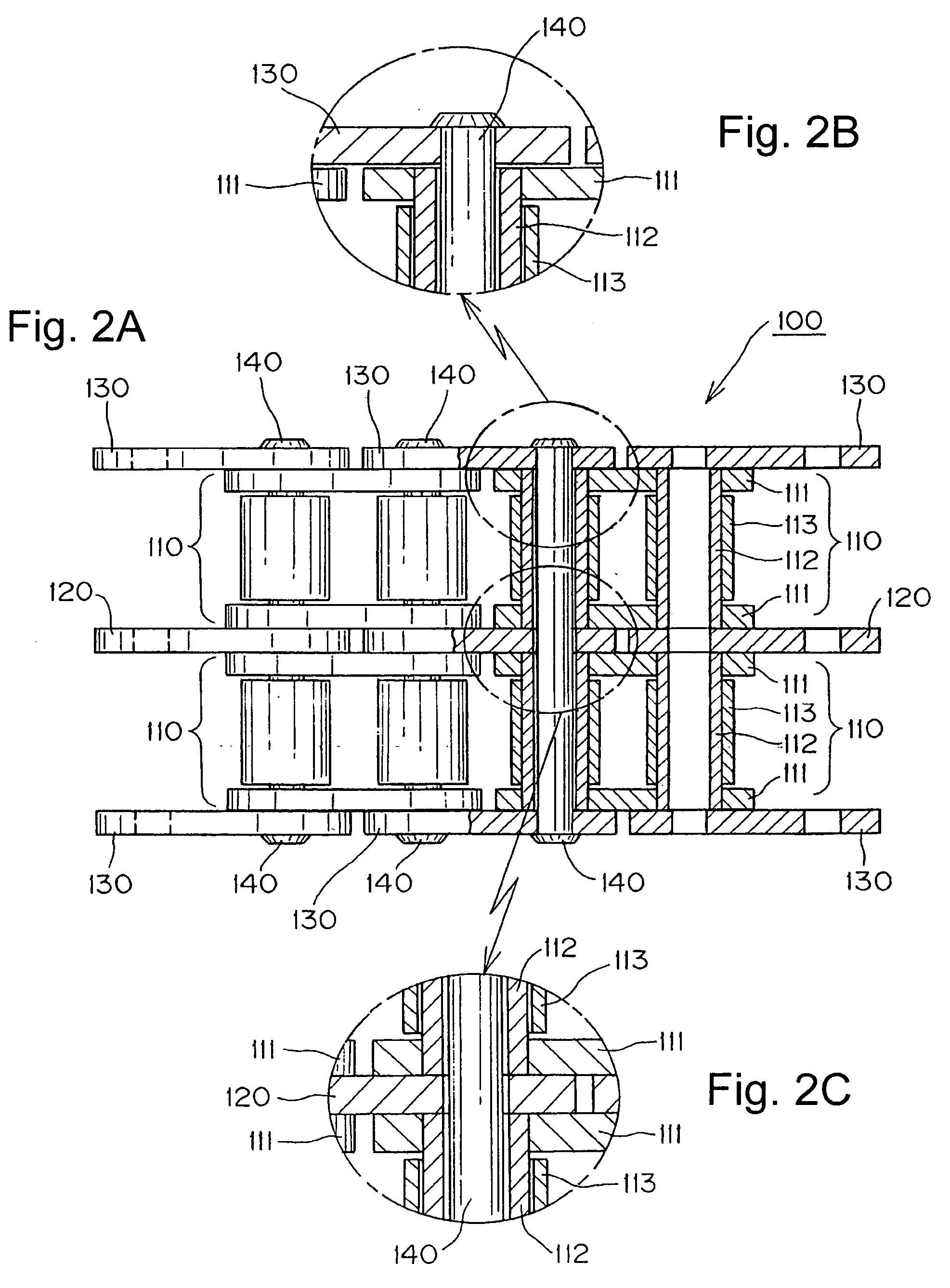
[0010]The transmitting multi-row chain of the present invention has rows of inner link units each comprising a pair of right and left inner plates into which a pair of front and rear bushes is press-fitted. The rows are disposed in parallel with each other through intermediate plates in a width direction of the chain. The inner link units in the rows are connected to each other in large numbers in the longitudinal direction of the chain by connecting pins press-fitted into outer plates disposed on the outermost sides in the width direction of the chain, the connecting pins being loosely fitted into pin holes of said intermediate plates. Each connecting pin is loosely fitted, or so-called clearance fitted, into a pin hole of the intermediate plate during manufacturing the chain, avoiding the need that the pin hole diameter of the intermediate plate and the pin diameter of the connecting pin are worked with high precision, unlike a conventional closely fitted multi-row chain. Simple disassembly and assembly of the chain such as disconnection and connection of the chain and the like can be attained. Further, since the intermediate plates are each formed with a plate height dimension smaller than each of the inner plate and outer plate, when the chain is traveled on a chain guide (sandwiched from both sides), it stably travels at only a level of the inner plate and the structure can contribute to making the entire chain lightweight.
[0011]According to a preferred feature of the present invention, the intermediate plate includes an arc-shaped bulged portion bulged in a plate shearing direction, which is generated by tension in a generally longitudinal direction of the chain. The bulge extends beyond the periphery which includes a virtual tangent line or arc between a pair of front and rear semi-circular shaped plate perimeters. The additional height of the arc-shaped bulged portion enhances the tensile strength and elastic modulus of the intermediate plate in the longitudinal direction of the chain to suppress the plastic deformation of the intermediate plate in a shearing direction of the plate, and the strength of the entire chain can be increased. And since a load balance in the chain width direction with respect to tension in the longitudinal direction of the chain is improved, even if a large power transmission load is generated, fatigue resistance of the chain can be significantly improved.
[0012]A further feature is that the bushes each rotatably mount a roller outside. Since the rollers engage with a sprocket and smoothly roll during the engagement with sprocket, wear of the chain can be reduced.

Problems solved by technology

However, there were problems in that when such a close fit between the intermediate plate and the connecting pin is adopted, the pin hole diameter in the intermediate plate and the pin diameter of the connecting pin must be worked with high precision during manufacturing of the chain and that even in the disassembling or assembling such as disconnecting or connecting a chain, the close fitting operation becomes troublesome and an excessive assembly effort is needed.
Further, since in the above-mentioned multi-row chain the intermediate plate has the same outer appearance as each of the inner plate and the outer plate, there was a problem in that the intermediate plate travels in an excessive frictional contact with the inner and outer plates as well as other members such as a chain guide and the like so that its slide resistance is increased and the operating noise is also increased.

Method used


Image

  • Transmitting multi-row chain
  • Transmitting multi-row chain
  • Transmitting multi-row chain

Examples


Embodiment Construction

[0021]The drawings illustrate a transmitting multi-row chain in which there are rows of link units each comprising a pair of right and left inner plates into which a pair of front and rear bushes is press-fitted. The rows are disposed in parallel with each other through intermediate plates in a width direction of the chain. The inner link units in each row are connected to each other in large numbers in the longitudinal direction of the chain by connecting pins press-fitted into outer plates disposed on the outermost side in the width direction of the chain. The connecting pins are loosely fitted into pin holes of said intermediate plates, and the intermediate plates are each formed with a plate height dimension smaller than each of said inner and outer plates whereby the chain strength is high, the chain is lightweight and the disassembly and assembly operation of the chain such as disconnecting and connecting of the chain and the like becomes simple. Any concrete embodiment of the...


PUM


Abstract

A transmitting multi-row chain in which the chain strength is high, the chain is lightweight, and the disassembly and assembly operation of the chain such as disconnecting and connecting of the chain and the like is simple. A transmitting multi-row chain has inner link units, each comprising a pair of right and left inner plates into which a pair of front and rear bushes is press-fitted. The inner link units are connected in rows to each other in large numbers in the longitudinal direction of the chain by connecting pins and the rows are disposed in parallel with each other through intermediate plates in a width direction of the chain. The connecting pins are press-fitted into outer plates disposed on the outermost sides in the width direction of the chain and are loosely fitted into pin holes of the intermediate plates. The intermediate plates are each formed in a plate height dimension smaller than the plate height dimension of each of the inner plate and the outer plate. The ends of the intermediate links are semi-circular with a bulge in the plate-shearing direction.

Description

FIELD OF INVENTION[0001]The present invention relates to a transmitting multi-row chain in which inner link units each comprising a pair of right and left inner plates into which a pair of front and rear bushes are press-fitted. The units are disposed in parallel with each other through intermediate plates in a width direction of the chain.BACKGROUND OF THE INVENTION[0002]In a transmitting mechanism having a large power transmission load it has been known to use a transmission chain with strength enhanced by the fact that a plurality of chains are disposed in parallel with each other in a width direction of the chain so as to be integrated or the like.[0003]And as such a conventional strength-enhanced transmission chain a multi-row chain has been known in which inner link units each comprising a pair of right and left inner plates into which a pair of front and rear bushes are press-fitted are disposed in parallel with each other through intermediate plates in a width direction of t...

Claims


Application Information

Patent Timeline
IPC IPC(8): F16G13/02
CPCF16M13/08F16G13/06F16G13/02
Inventor TAMIYA, ATSUHIRO
Owner TAMIYA ATSUHIRO
Learn More