Multi-speed automatic transmission adapted for motor vehicle

a multi-speed automatic transmission and motor vehicle technology, applied in mechanical equipment, transportation and packaging, gearing, etc., can solve the problems of multi-speed automatic transmission, not avoiding, and great difficulties in installation on a motor vehicl

Inactive Publication Date: 2007-11-01
KYOWA METAL WORKS
View PDF7 Cites 14 Cited by
  • Summary
  • Abstract
  • Description
  • Claims
  • Application Information

AI Technical Summary

Benefits of technology

[0011]Therefore, thus-using of the moving-off clutch can remove a fluid coupling or a torque converter, and accordingly an axial length of the automatic transmission can be set smaller.

Problems solved by technology

These gear sets and friction elements are arranged in series in an axial direction of the transmission, which requires space longer in the axial direction and causes great difficulties for its installation on a motor vehicle such as a front-engine front-drive (FF) vehicle and a rear-engine rear-drive (RR) vehicle, in which the transmission is arranged in a lateral direction of a vehicle body.
This conventional multi-speed automatic transmission, however, can not avoid arrangement of four friction elements, consisting of two clutches and two brakes, from being arranged in series on an axis of one of the planetary gear set, although its axial length can be shorten in comparison with the former conventional automatic transmission.
Especially, one brake can not avoid being arranged at an outer side of a chain connecting a first planetary gear set and a second planetary gear set.

Method used


Image

  • Multi-speed automatic transmission adapted for motor vehicle
  • Multi-speed automatic transmission adapted for motor vehicle
  • Multi-speed automatic transmission adapted for motor vehicle

Examples


first embodiment

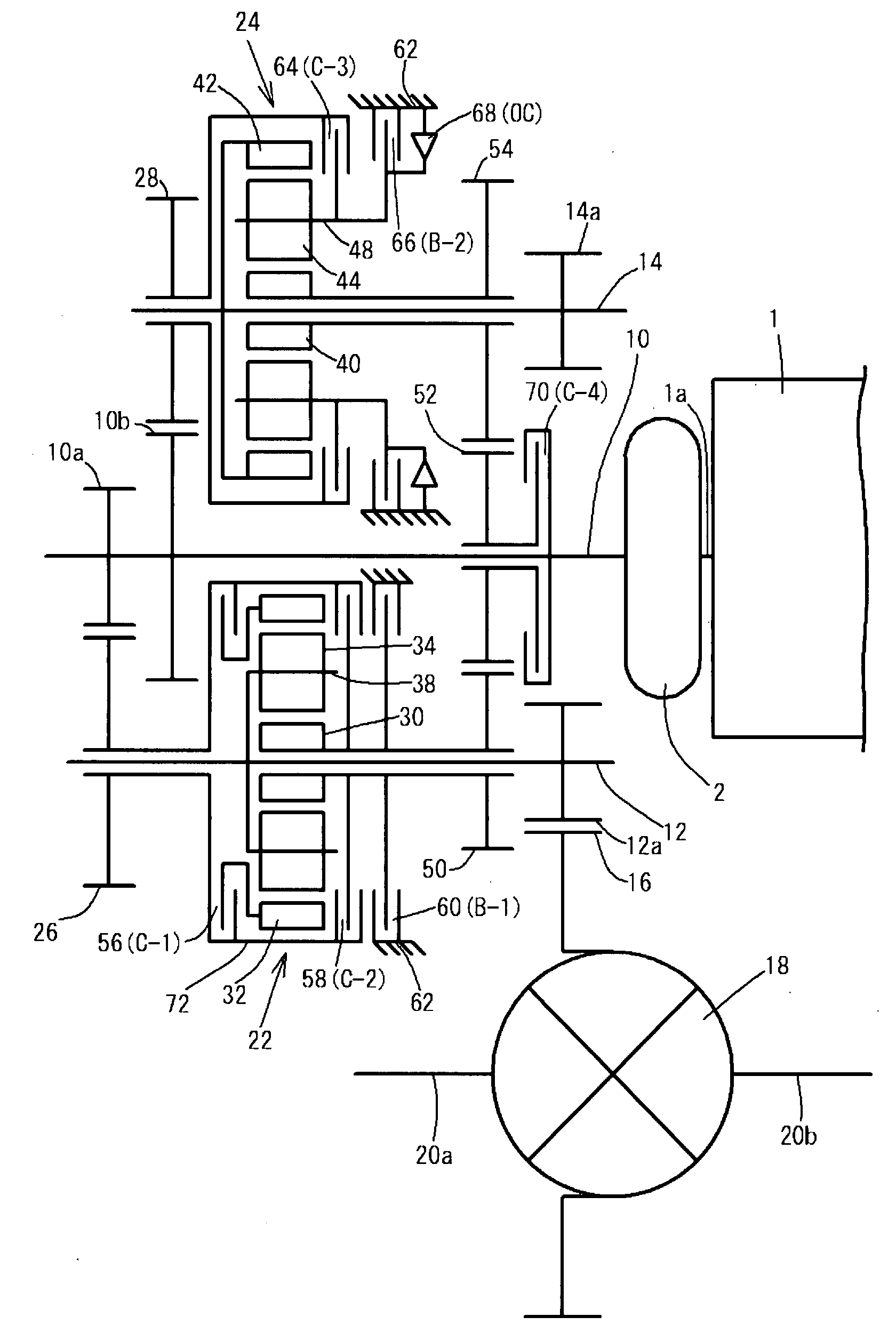
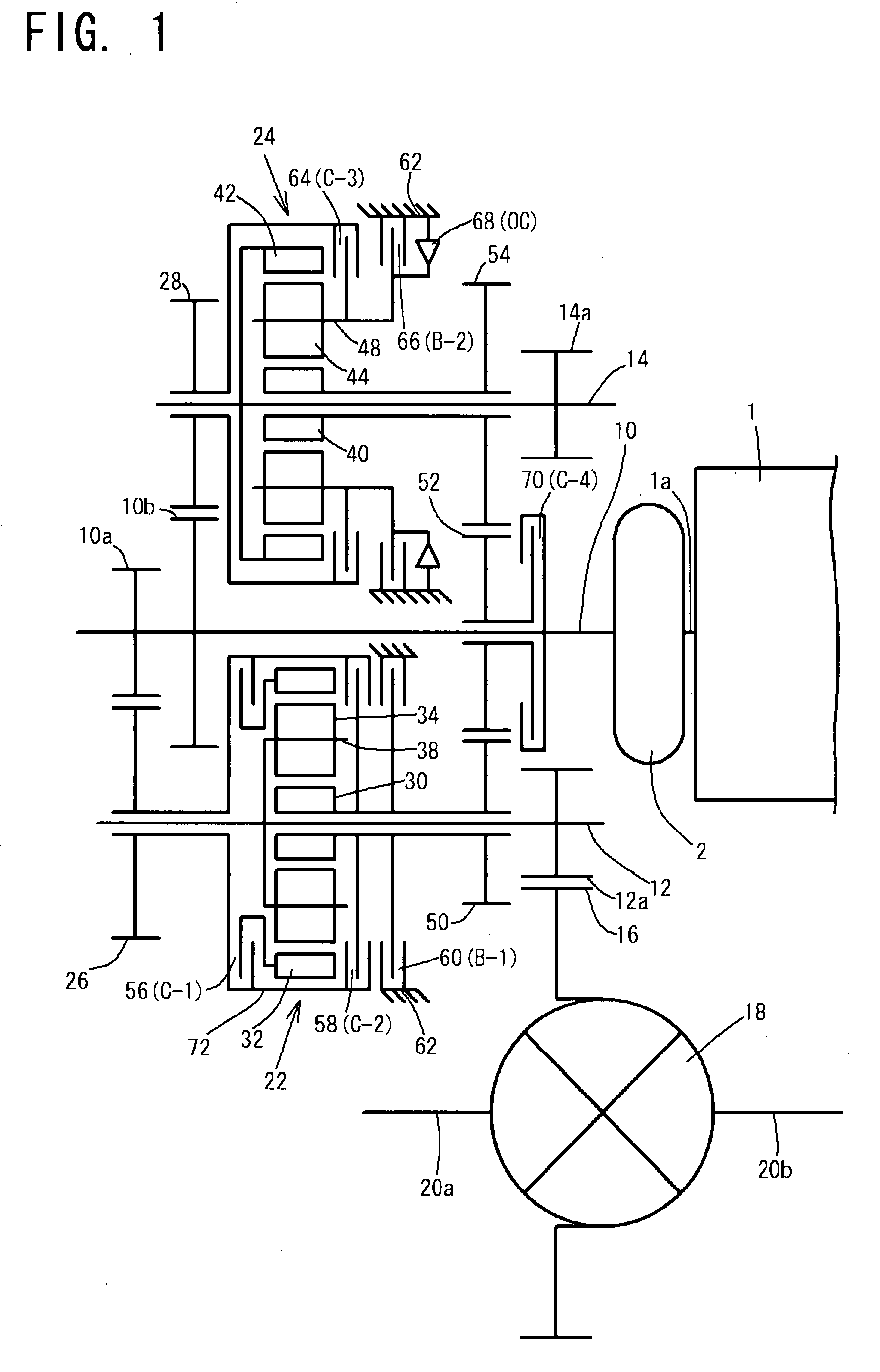
[0034]The multi-speed automatic transmission of the first embodiment will be described.

[0035]Friction elements, consisting of the first to fourth clutches 56, 68, 64 and 70, and the first and second brake 60 and 66, are operated based on vehicle speed, an accelerator pedal angle, a select-lever position and others in order to obtain optimum gears according to a shift table shown in FIG. 3. Incidentally, the one-way clutch 68 is mechanically and automatically operated according to a rotation state of the second pinion carrier 48 also as shown in FIG. 3.

[0036]In the shift table of FIG. 3, “D”, “R” and “L” indicate a forward drive position, a reverse position and a forward low drive position of the select lever position, respectively and “1st” to “8th” and “R-1” and “R-2” indicate first to eighth speeds and first to second reverse speed, respectively. “C-1” to “C-4” indicates the first to fourth clutches 56, 58, 64 and 70, and “B-1”, “B-2” and “OC” indicate the first brake 60, the seco...

second embodiment

[0068]Next, an automatic transmission of a second embodiment according to the present invention will be described with reference to the accompanying drawings of FIGS. 4 and 5.

[0069]As shown in FIG. 4, the automatic transmission of the second embodiment has a first planetary gear set 22 arranged on a first output shaft 12 and a second planetary gear set 24 arranged on a second output shaft 14 similarly to those of the first embodiment. An intermediate member 72 is provided at a radially-outer side of the first planetary gear set 22, and is equipped with a moving-off clutch 74, namely a starting clutch, and a first clutch 56 at a first input driven gear (26) side of the first planetary gear set 22. The moving-off clutch 74 is capable of connecting the intermediate member 72 and the first input driven gear 26 with each other, and the first clutch 56 is capable of connecting the intermediate member 72 and a first ring gar 25 with each other. The intermediate member 72 is also provided w...

third embodiment

[0081]Next, a multi-speed automatic transmission of a third embodiment according to the present invention will be described with reference to the accompanying drawing of FIG. 6.

[0082]In the automatic transmission of the third embodiment, a moving-off clutch 74 is provided on an input shaft 10, not on an intermediate member 72 like the second embodiment, at an end portion, opposite to an engine 1, of the input shat 10 so that it can engage the input shaft 10 and a first input drive gear 10a. Accordingly, the input shaft 10 is connectable with the intermediate member 72 through the first input drive gear 10a and a first input driven gear 26.

[0083]A first brake 60 is a multi-plate brake, being different from that of the second embodiment.

[0084]The other parts are constructed similarly to those of the second embodiment, and n operation table is the same as that of the second embodiment shown in FIG. 5. Descriptions of the construction and operation of the third embodiment are omitted.

[0...


PUM


Abstract

A multi-speed automatic transmission includes a first planetary gear set and a second planetary gear set, which are arranged in parallel on a first output shaft and a second output shaft, respectively. An input shaft is connectable with a first ring gear through first input drive and driven gears of the input shaft and the first output shaft, being connectable with a second pinion carrier through a second input drive and driven gears of the input shaft and the second output shaft. The first output shaft is connectable with a first pinion carrier, the second output shaft being connectable with a second ring gear. A second pinion carrier is fixable to a transmission case. The first and second sun gears are connectable with the input shaft through the first input drive and driven gears and through the intermediate gear, being fixable to the transmission case.

Description

BACKGROUND OF THE INVENTION[0001]1. Field of the Invention[0002]The present invention relates to a multi-speed automatic transmission, adapted for a motor vehicle, which has a planetary gear sets and is arranged in a lateral direction of its vehicle body.[0003]2. Description of the Related Art[0004]Recently, automatic transmissions mounted on motor vehicles require more forward speeds, for example more than six forward speeds, in order to improve fuel consumption, exhaust emission purification, and accelerating performance. Such a conventional multi-speed automatic transmission for a motor vehicle is disclosed in Japanese patent laid-open publication No. (Tokkaihei) 04-219553. This conventional multi-speed automatic transmission has two gear sets, one of which is a Ravigneaux type planetary gear set, or three gear sets associated with five friction elements to provide forward 6-speeds. These gear sets and friction elements are arranged in series in an axial direction of the transmis...

Claims


Application Information

Patent Timeline
Patent Type & Authority Applications(United States)
IPC IPC(8): F16H3/44
CPCF16H37/04F16H2003/0931F16H2200/006F16H2200/2051F16H2200/2007F16H2200/2046F16H2200/2048F16H2200/0086F16H3/58F16H3/44
Inventor HIRAIWA, KAZUYOSHI
Owner KYOWA METAL WORKS
Why Eureka
Try Eureka