
Positive contrast MRI using positive and negative field inhomogeneity

Active Publication Date: 2007-11-01
THE BOARD OF TRUSTEES OF THE LELAND STANFORD JUNIOR UNIV
View PDF3 Cites 2 Cited by
  • Summary
  • Abstract
  • Description
  • Claims
  • Application Information

AI Technical Summary

Benefits of technology

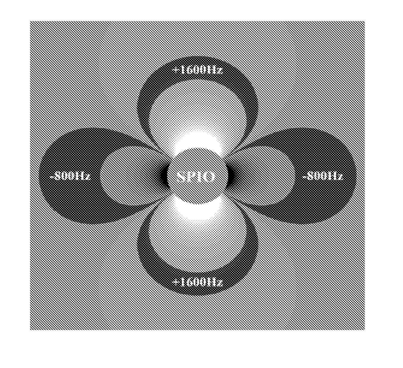
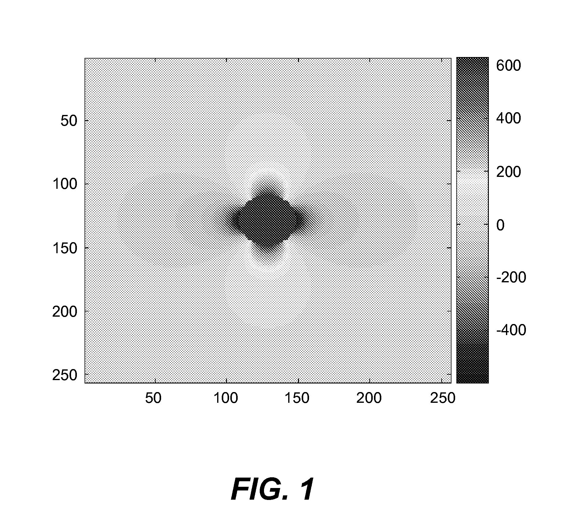
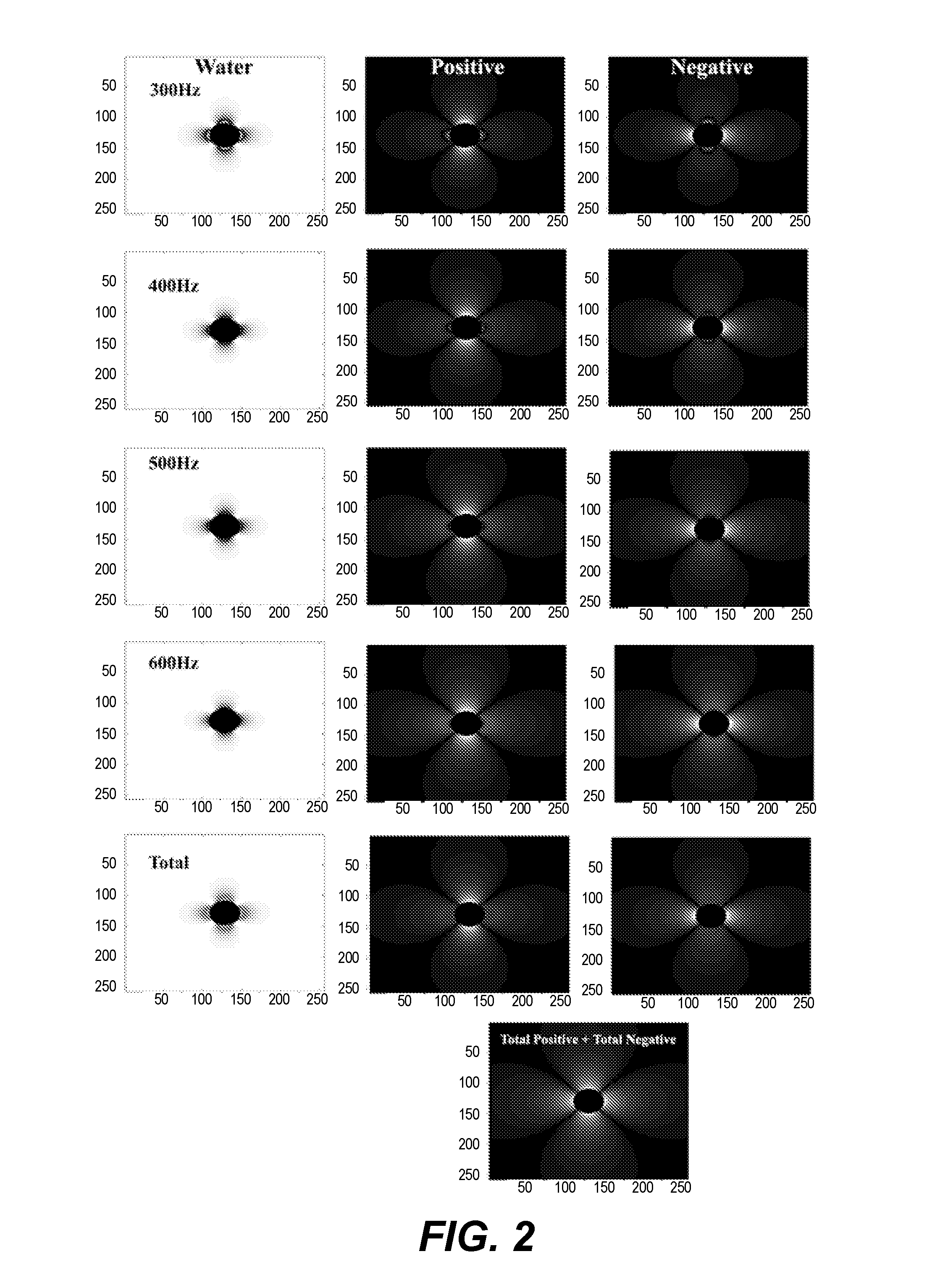
[0008] In one embodiment, an on-resonance and two off-resonance signals are selected including a negative frequency offset signal due to negative equatorial lobes and a positive frequency offset due to the positive polar lobes. The off-resonance signals can be summed to identify the magnetic susceptibility labeled regions, The on-resonance signal provides accurate registration with anatomic images.

Problems solved by technology

Imaging in the presence of severe magnetic field inhomogeneities has been very challenging for magnetic resonance imaging applications.
The ability to image directly adjacent to metallic implants for example, has been very limited due to image distortion and markedly shortened T2*.
Although effective, this method is relatively insensitive and non-specific.
Thus, the conspicuity of collections of these particles visualized with T2* sensitive pulse sequences is limited by the fact that signal is dark in a background of bright signal in the remainder of the image.

Method used


Image

  • Positive contrast MRI using positive and negative field inhomogeneity
  • Positive contrast MRI using positive and negative field inhomogeneity
  • Positive contrast MRI using positive and negative field inhomogeneity

Examples


Embodiment Construction

[0015] In accordance with the invention, the acquisition of multiple images at slightly different time echo time shifts, will allow the separation of on-resonance spins from off-resonance spins by encoding this information in the received signal. The excitation pulse can be a standard broadband excitation that will excite all spins. The separation of on- and off-resonance spins is then performed on the received signal.

[0016] Consider now the theory underlying the invention. Assume the presence of two or more species, at least one of which is on-resonance. One of the off-resonance species could be fat, in which case a fat image is obtainable along with a on-resonance image and a SPIO image, for example. The signal detected in a voxel containing these spins is s⁡(tn)=ρo+∑m=1M⁢ ⁢ρm⁢ⅇⅈ2π⁢ ⁢Δ⁢ ⁢fm⁢tn(1)

ρo is the on-resonance component, and ρm is the mth off-resonance component, m=1, . . . ,M. Δƒm is the off-resonance frequency of the mth component, and tn(n=1, . . . ,N) is the echo tim...


PUM


Abstract

The acquisition of multiple images at slightly different time shifts from the spin echo (or from TE=0 for gradient echo sequences), allows the separation of on-resonance spins from off-resonance spins by encoding this information in the received signal. The excitation pulse can be a standard broadband excitation that will excite all spins. The separation of on- and off-resonance spins is then performed on the received signal. The polar and equatorial lobes of a magnetic particle such as SPIO produce signals from excited water molecules near the particle which are frequency offset above and below the frequency of signals from water molecules unaffected by the particle.

Description

BACKGROUND OF THE INVENTION [0001] This invention relates generally to magnetic resonance imaging (MRI), and more particularly the invention relates to the use of MRI in tracking magnetically labeled cells or objects in the presence of magnetic field inhomogeneity using positive contrast. [0002] Magnetic resonance imaging (MRI) requires placing an object to be imaged in a static magnetic field, exciting nuclear spins in the object within the magnetic field, and then detecting signals emitted by the excited spins as they process within the magnetic field. Through the use of magnetic gradient and phase encoding of the excited magnetization, detected signals can be spatially localized in three dimensions. [0003] Contrast agents incorporating super-paramagnetic iron-oxide (SPIO) nanoparticles have shown much promise as a means to visualize labeled cells using MRI. The small size of the particles (<100 nm) facilitates transport across cell membranes, and the low toxicity allows for la...

Claims


Application Information

Patent Timeline
IPC IPC(8): A61B5/05
CPCG01R33/5601
Inventor REEDER, SCOTT B.GOLD, GARRY E.
Owner THE BOARD OF TRUSTEES OF THE LELAND STANFORD JUNIOR UNIV
Learn More