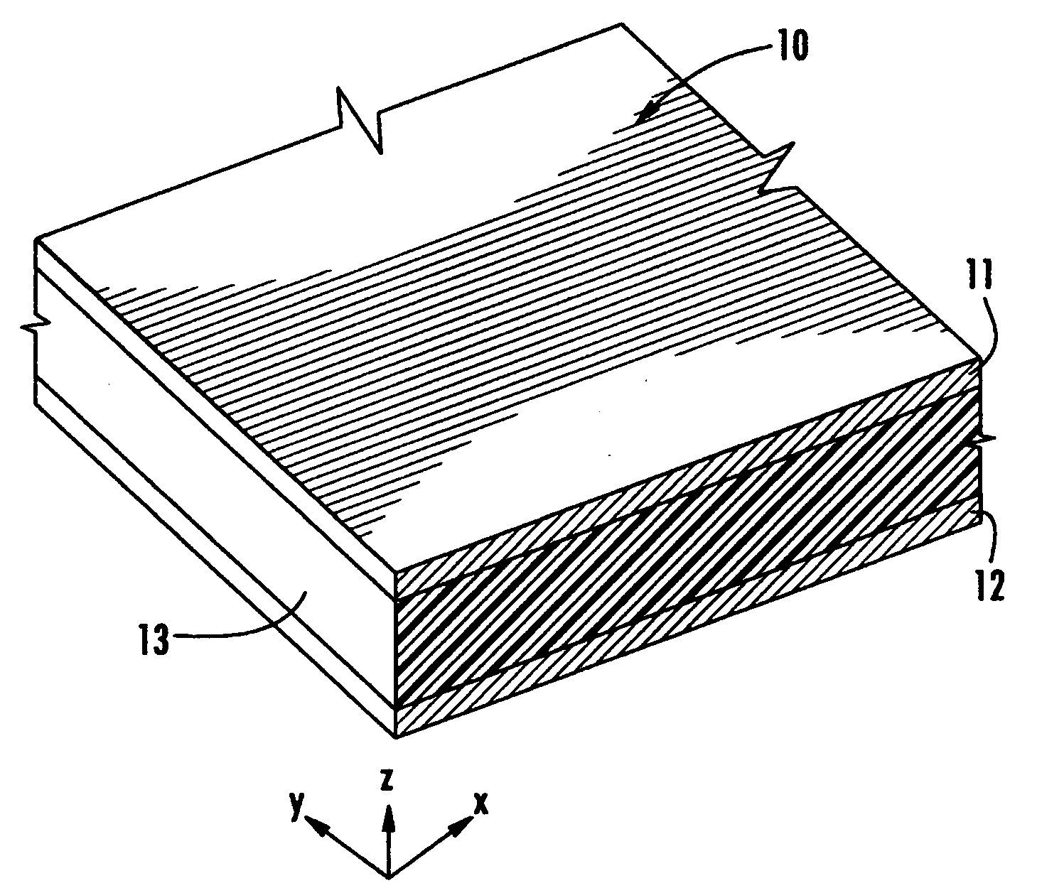
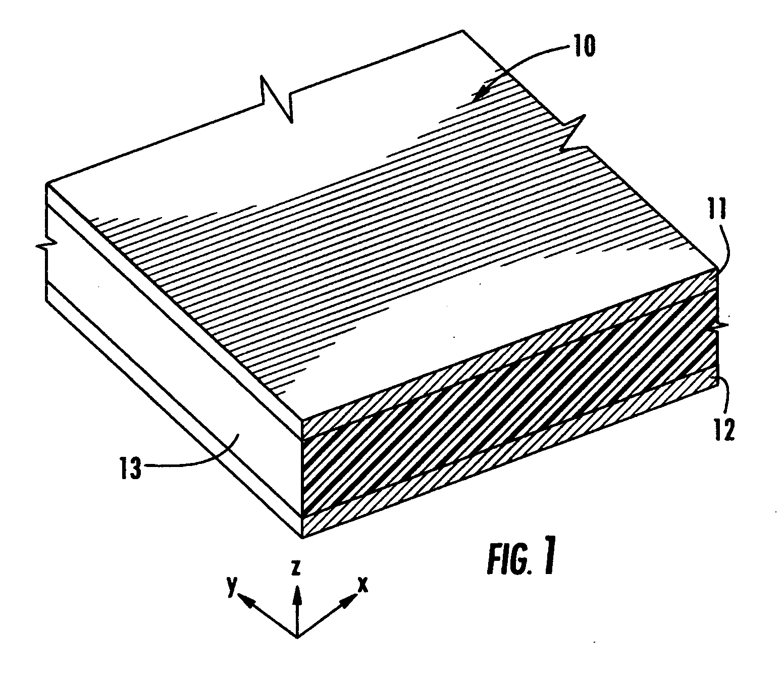
Composite panels

a technology of composite panels and foam, applied in the field of composite panels, can solve the problems of poor compressive strength of balsa, high cost, environmental concerns, etc., and achieve the effect of improving the bonding strength of honeycomb and foam, reducing the surface area of honeycomb, and reducing the resistance of honeycomb

Inactive Publication Date: 2007-11-08
EDWARDS CHRISTOPHER M
View PDF7 Cites 155 Cited by
  • Summary
  • Abstract
  • Description
  • Claims
  • Application Information

AI Technical Summary

Problems solved by technology

Balsa provides excellent compressive strength but is also expensive, has environmental concerns and is prone to rotting if it becomes wet either as a result of the core being breached or from moisture seeping through the edges of the panel.
Honeycomb is more expensive than foam and has very limited surface area for bonding to the skin.
This can be problematic for aesthetics because of the read-through of the honeycomb pattern when skins are laminated onto it because all of the lamination pressure acts on the edges of the honeycomb cells.
However, foamed polymer core composite panels typically have lower physical properties than honeycomb core sandwich panels of the same weight.

Method used


Image

  • Composite panels
  • Composite panels
  • Composite panels

Examples


second embodiment

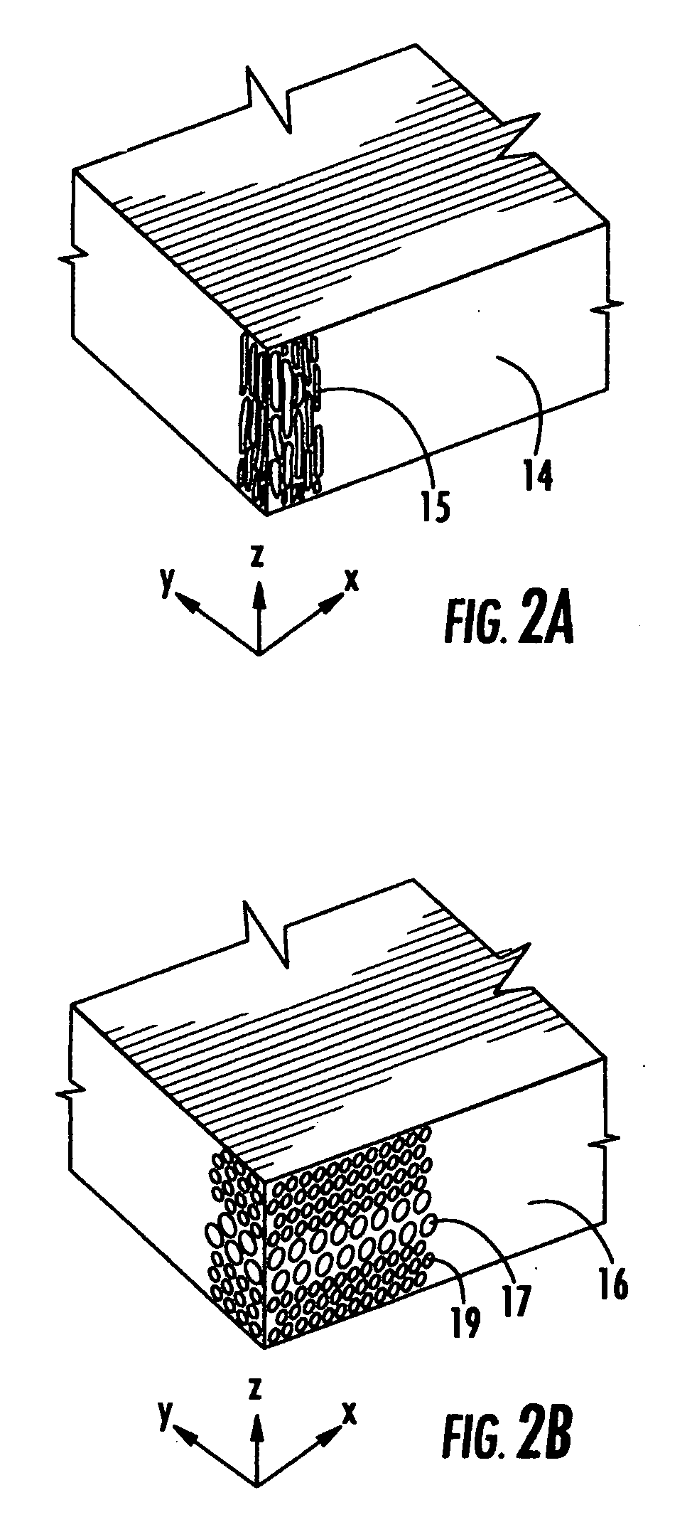
[0023]Referring now to FIG. 2b, therein is shown a core of foamed polymer 16 in which the bubbles which make up the foam are essentially round and vary in size, wherein the bubbles 17 which are close to the center of the core 16 are larger than the bubbles 19 which are closer to the surface of the core 16 (preferably the bubbles are progressively smaller toward the surface of the core 16). As a result the material at the center has a lower density while the material at the surface has a higher density. The higher density of the material at the surface provides greater strength, particularly compressive strength and also provides greater area to bond to the skins.

third embodiment

[0024]Referring now to FIGS. 3a, 3b and 3c, therein is shown the instant invention wherein the core material 20, 22 and 24, respectively, consists of a foamed polymer which contains discrete strands, planes or geometric shapes of more dense or solid thermoplastic material 21, 23 and 25, respectively, which are continuous in the ‘z’ direction as shown. Such geometric shapes may be, for example, discrete rods, and strips or round, square or hexagonal tubes. These more dense or solid regions increase the compressive properties of the foam. The increase in strength and stiffness is out of proportion to the increase in weight because although the solid material of these pillars is thin, it is supported by the foam around it so that it is less likely to buckle when subjected to compressive loads. The more dense or solid material may be the same material (preferably a thermoplastic polymer) as the material of the foam or may be a different but compatible material. The percentage of more de...

fourth embodiment

[0025]Referring now to FIGS. 4a, 4b and 4c, therein is shown the instant invention wherein the geometric shapes of the more solid or dense material in the Z direction 27, 29 and 31, respectively, are connected to form a continuous array in the foamed polymer 26, 28 and 30, respectively. Such connectivity further enhances the compressive strength of the foam as each element may now receive support from adjacent elements when overloaded. The connectivity also increases the shear strength and stiffness of the core structure. Such materials are commercially available from The Dow Chemical Company under the trade name “STRANDFOAM”.


PUM

PropertyMeasurementUnit
densityaaaaaaaaaa
densityaaaaaaaaaa
densityaaaaaaaaaa

Abstract

A composite panel consisting of outer skins and an inner core consisting of a foamed polymer, wherein the structure or properties of the inner core are anisotropic. The composite panel can be made by applying external heat and pressure to melt a skin of thermoplastic composite and an initial thickness of a thermoplastic core which has anisotropic properties causing the skin and core to fuse together followed by cooling the fused structure. The composite panel can be made by applying external heat and pressure to melt layers of a thermoplastic adhesive positioned between the outer skins and an inner core consisting of a foamed polymer, wherein the structure or properties of the inner core are anisotropic, so that the skins are bonded to the core by the melted layers of the thermoplastic adhesive followed by cooling the bonded structure.

Description

[0001]This application claims the benefit of priority to U.S. Provisional Patent Application Ser. No. 60 / 798,628 filed May 8, 2006.BACKGROUND OF THE INVENTION[0002]The instant application relates to sandwich panels articles and methods for their manufacture and more specifically, the instant application relates to sandwich panels with low density cores and methods for their manufacture.[0003]Sandwich panels are well known and widely used in many applications for the combination of mechanical properties and low weight. For large structures such as buildings, boats, containers, truck boxes and the like, sandwich panels consisting of surface skins of relatively thin rigid material sandwiching a low density core are often used. These sandwich panels are particularly advantageous because the skin core structure is extremely efficient at resisting loads, especially bending loads. The reason for this is that when a bending load is applied to a structure the outer portions of the structure ...

Claims


Application Information

Patent Timeline
Patent Type & Authority Applications(United States)
IPC IPC(8): E04C2/26
CPCB32B5/18B32B2607/00B60R13/0225B60R13/0243B60R13/0268E04C2/292E04C2/296B32B5/145B32B15/046B32B21/00B32B21/047B32B27/065B32B27/08B32B27/306B32B27/32B32B2250/40B32B2266/0228B32B2266/0235B32B2266/025B32B2266/0264B32B2307/706B32B2307/72B32B2479/00B60R13/01
Inventor EDWARDS, CHRISTOPHER M.
Owner EDWARDS CHRISTOPHER M
Why Eureka
Try Eureka