
Integrated vacuum blocking valve

a vacuum blocking valve and integrated technology, applied in the direction of condensed fuel collection/return, charge feed system, non-fuel substance addition to fuel, etc., can solve the cost of a canister purge system, increase predictability, reduce the vapor generation rate of fuel tanks

Inactive Publication Date: 2007-11-08
SIEMENS CANADA LTD
View PDF10 Cites 6 Cited by
  • Summary
  • Abstract
  • Description
  • Claims
  • Application Information

AI Technical Summary

Benefits of technology

[0009] Other objects, features and characteristics of the present invention, as well as the methods of operation and the functions of the related elements of the structure, the combination of parts and economics

Problems solved by technology

This increases the predictability of the purge flow fuel vapor content and reduces the vapor generation rate within the fuel tank.
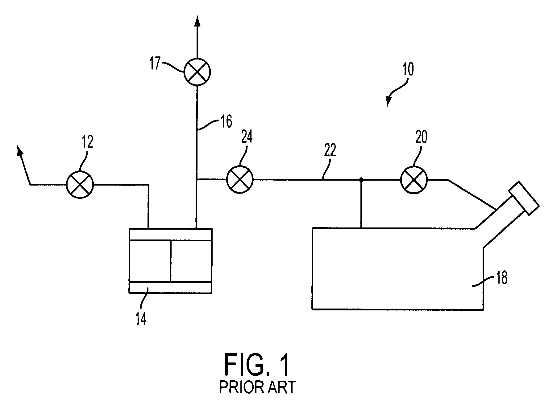
Thus, there is a need to integrate the vapor purge valve with a canister to reduce the number of parts and thus the cost of a canister purge system.

Method used


Image

  • Integrated vacuum blocking valve
  • Integrated vacuum blocking valve
  • Integrated vacuum blocking valve

Examples


first embodiment

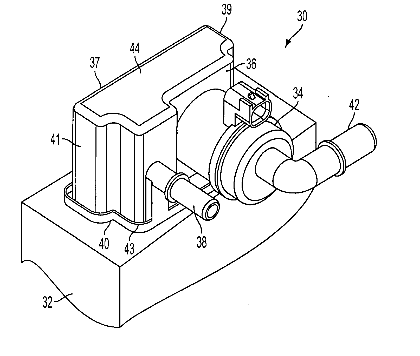
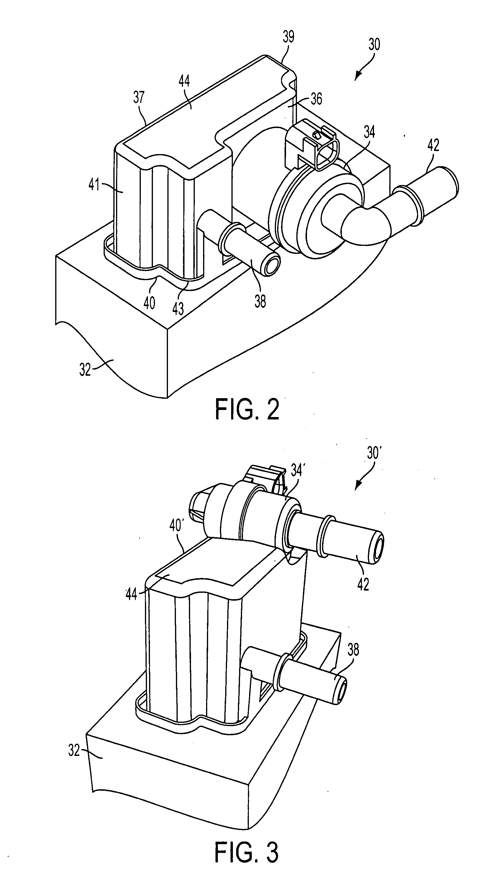
[0014] With reference to FIG. 2, a carbon canister assembly is shown, generally indicated at 30 for use in a vehicle canister purge system of the type shown in FIG. 1. The assembly 30 includes a canister cap 40 and canister 32, and an integral vapor blocking valve 34 mounted directly to a front 36 of the canister cap 40 and in fluid communication with the canister 32. The canister cap 40 has a front 36, a back 37, sides 39 and 41, a top 44 and a bottom 43 is attached to the canister 32. The canister cap 40 can be considered to be part of the canister 32. The canister 32 contains carbon in the conventional manner to adsorb hydrocarbon vapor produced in a fuel storage system of a vehicle in engine-off conditions. The canister cap 40 includes a port 38 that is constructed and arranged to fluidly communicate with a canister vent valve (not shown) for purging any fuel vapor trapped within the canister 32. The cap 40 is welded to a top of the canister 32 to close an opening in the caniste...

second embodiment

[0016] With reference to FIG. 3, a carbon canister assembly is shown, generally indicated at 30′. The assembly 30′ includes a canister 32, a canister cap 40′, and an integral vapor blocking valve 34′ mounted directly to a top 44 of the canister cap 40′. The canister cap 40′ includes the port 38. The vapor blocking valve 34′ includes the port 42 that is constructed and arranged to fluidly communicate with a vehicle fuel tank (not shown) and operate in the manner discussed above.

[0017] The vapor blocking valve 34, 34′ can have a housing that is molded with the canister cap 40, 40′ or can be attached directly thereto in any known manner. Since the vapor blocking valve 34, 34′ is integral with the canister assembly 30, there is no need for an extra hose between the canister and vapor blocking valve, nor is there a need to provide an additional mounting bracket to mount the vapor blocking valve. Thus, costs are reduced.

[0018] Both of the configurations shown in FIGS. 2 and 3 maintain an...


PUM


Abstract

A canister assembly (30) is provided for canister purge system of a vehicle. The assembly includes a canister (32) constructed and arranged to adsorb hydrocarbon vapor. A vapor blocking valve (34) is integral with the canister and is in fluid communication therewith. The vapor blocking valve has a port (42) constructed and arranged to fluidly communicate with a fuel tank of the vehicle. The vapor blocking valve is constructed and arranged to permit communication between the fuel tank and canister and, under certain conditions, to isolate the fuel tank from the canister. Since the vapor blocking valve is integral with the canister, additional hoses and mounting brackets are not required.

Description

[0001] This application claims the benefit of the earlier filing date of U.S. Provisional Application No. 60 / 746,565, filed on May 5, 2006, which is incorporated by reference herein in its entirety.FIELD OF THE INVENTION [0002] This invention relates to a vehicle canister purge system and, more particularly, to a blocking valve made integral with a carbon canister. BACKGROUND OF THE INVENTION [0003] Charcoal vapor canisters attached in series to a vehicle's fuel storage system are used to adsorb hydrocarbon vapor produced in the fuel storage system in engine-off conditions. With reference to FIG. 1, during engine-on vehicle operations, air enters a canister purge system 10 through a canister vent valve 12, purges any fuel vapor trapped within the canister 14, and proceeds to purge line 16. Meanwhile, fuel vapor exits the fuel tank 18 through a vent valve 20 via line 22 and through a vapor blocking valve 24 into the purge line 16. This air / vapor mixture then enters the cylinder head ...

Claims


Application Information

Patent Timeline
IPC IPC(8): F02M25/08F02M33/02
CPCF02M25/0836
Inventor WILLIAMS, BENJAMIN DOMINICK MANTON
Owner SIEMENS CANADA LTD
Learn More