
Method for Operating a Well Jet Device in the Conditions of a Formation Hydraulic Fracturing

Inactive Publication Date: 2007-11-08
KHOMYNETS ZINOVIY DMITRIEVICH
View PDF5 Cites 8 Cited by
  • Summary
  • Abstract
  • Description
  • Claims
  • Application Information

AI Technical Summary

Benefits of technology

[0008] The objective of this invention is to increase intensification of works on studying, testing and conditioning wells as well as to improve reliability of obtained data on preparedness of a well for operation in the working mode.
[0010] An analysis of the well jet device operation has shown that the operational reliability may be increased both by optimizing the operation sequence during testing and developing wells and by making the operation sequence in the well more optimized.
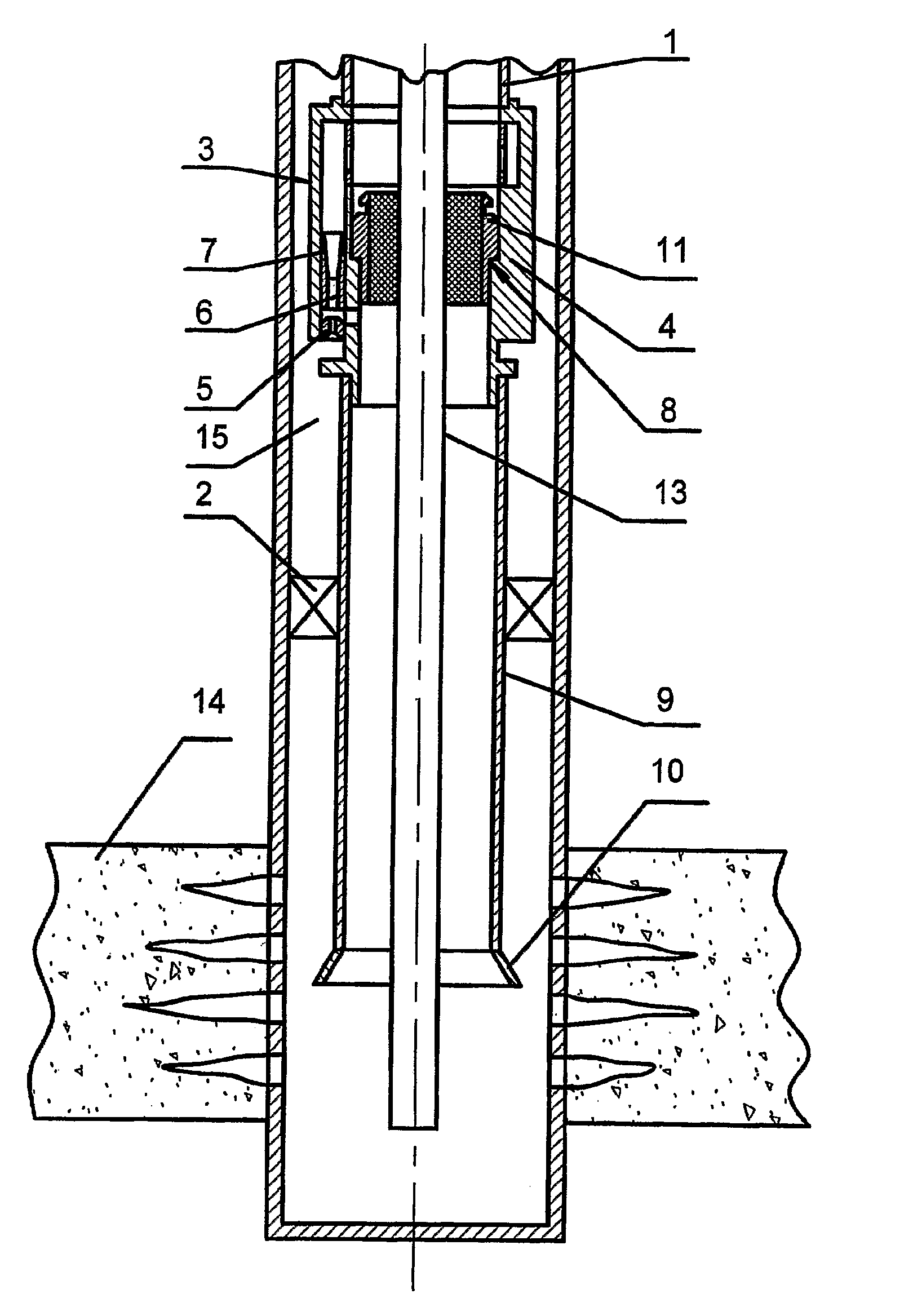
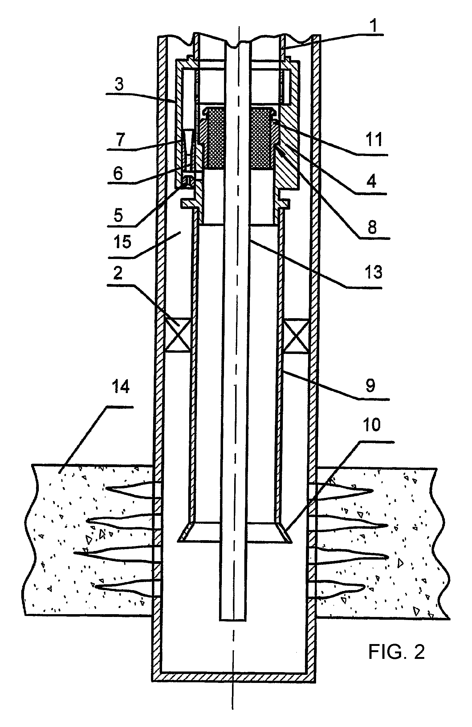
[0011] It has been established that the above sequence of operations enables to most effectively use the equipment arranged on the flow string when carrying out works on studying and testing productive formations in rocks, creating conditions for obtaining most complete and reliable data on the status of productive formations. The installed flexible tube passed through the sealing unit with the possibility of being moved axially enables carry out high-quality works on conditioning a well for operating in the working mode. A well may be treated and prepared for operation without repeated installation of the well jet device, which also enables to accelerate and simplify the procedures of testing and conditioning a well for operation. By creating a differential pressure drawdown the jet pump creates a preset differential pressure in a well, and a fluid for washing the well bottom is delivered into the well by the flexible tube, which enables to remove both any propant that is not fixed in cracks and the fluid used for hydraulic fracturing together with chemical agents and products of their reactions with minerals contained in the productive formation. At this point, in order to wash the well efficiently it is important to observe the optimal relation between pressure values in the flexible tube (Pf) and pressures (Pw) of the liquid working medium in the well annulus, which must be maintained within the range (Pf:Pw)≦0.98. At the same the possibility of monitoring a differential pressure drawdown value and the above-mentioned required pressure relation by controlling the pumping speed of the liquid working medium. Further, it is important to determine not only an optimal sequence of operation in the well, but also their duration. It has been established that after treatment of a productive formation it is sufficient to pump out fluid in a quantity equal to or less than twice the quantity of a hydraulic fracturing fluid or a mixture of a hydraulic fracturing fluid with chemical agents that has been pumped into the productive formation, and then the supply of a fluid for washing the well bottom may be stopped, and after it, but not earlier than in 5 minutes the supply of a liquid working fluid to the jet pump nozzle may be stopped as well.
[0012] Thus, the above-stated totality of interdependent parameters and the stated sequence of operations will ensure achievement of the invention objective—to increase intensification of works on studying, testing and conditioning a well, and increase reliability of data obtained on preparedness of a well for operation in the working mode.

Problems solved by technology

However, this operating method does not enable to study near-well areas, which in a number of cases leads to a reduced efficiency of works on intensifying well operation due to lack of information on behavior of perforated formations.
Thus, work efficiency of draining a well does not give expected results.
However, this operating method does not enable using its capabilities in full, since it does not enable conducting both treatment of a productive formation and washing of the well bottom, which narrows the field of application of that method of operating a well jet unit.
Moreover, its operation parameters and operation sequence are not optimized for carrying out works on hydraulic fracturing of a productive formation and washing of the well bottom during one study cycle in a well.

Method used


Image

  • Method for Operating a Well Jet Device in the Conditions of a Formation Hydraulic Fracturing
  • Method for Operating a Well Jet Device in the Conditions of a Formation Hydraulic Fracturing
  • Method for Operating a Well Jet Device in the Conditions of a Formation Hydraulic Fracturing

Examples


Embodiment Construction

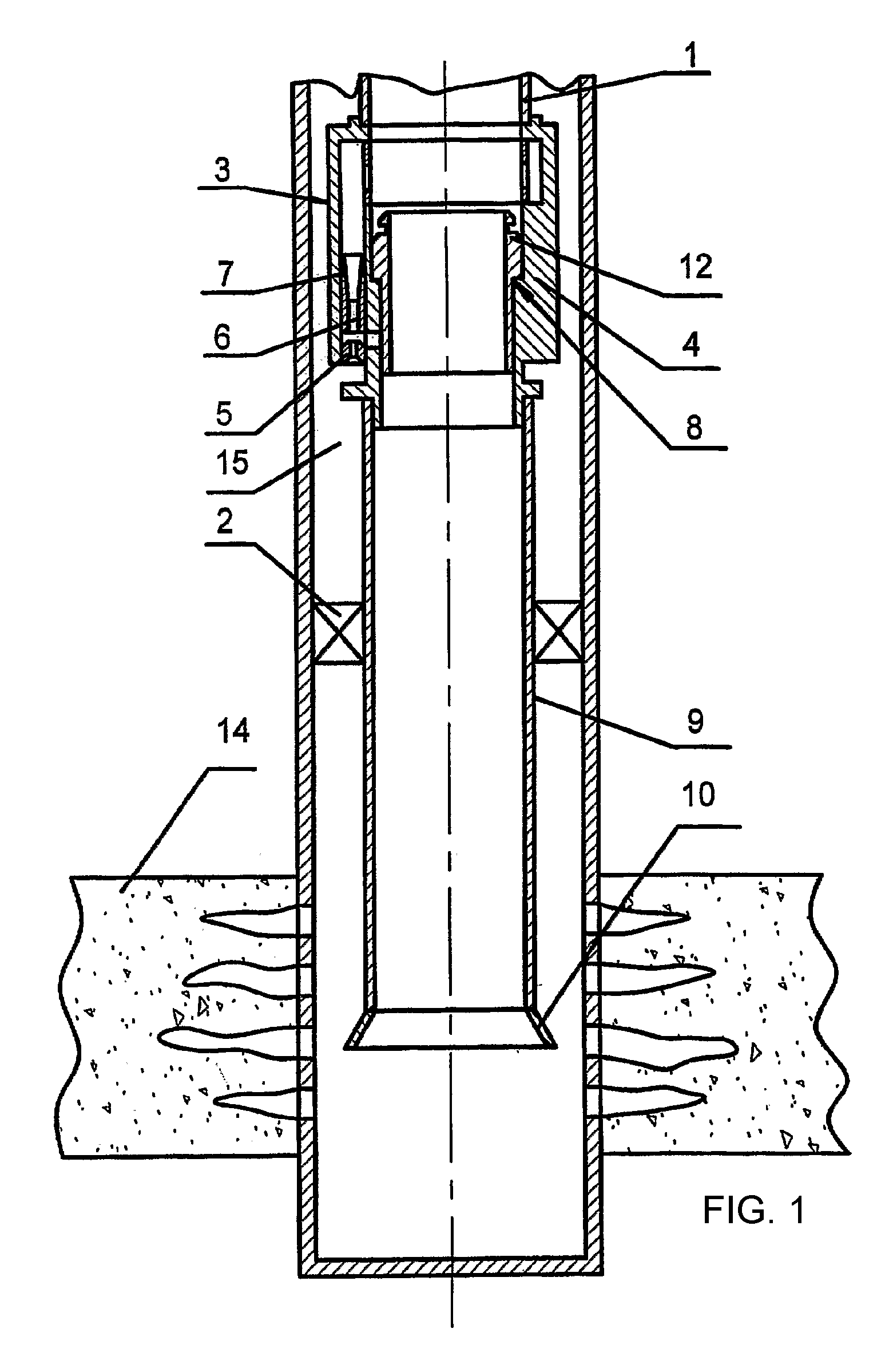
[0015] A well jet device for implementing the inventive method comprises, all being installed on a flow string 1, a packer 2 with a through passage, a jet pump 3 in the body 4 of which a nozzle 5 and a mixing chamber 6 with a diffuser 7 are arranged as well as a stepped through passage 8 is made, and a stem 9 with an inlet funnel 10 arranged below the jet pump 3. A sealing unit 11 or a blocking insert 12 may be arranged in the stepped through passage 8. A flexible tube 13 is passed through the sealing unit 11, the lower end of the flexible tube 13 being arranged below or at the level of the lower perforation interval of a productive formation 14. The jet pump 3 and the packer 2 are arranged in the well above the productive formation 14.

[0016] The inventive method for operating a well jet device at hydraulic fracturing of a formation is carried out as follows.

[0017] The jet pump 3 with the stepped through passage 8 made in the body 4 of the said pump and the packer 2 with the throu...


PUM


Abstract

The inventive device operating method consists in running a jet pump into a well, in releasing a packer above a productive formation, in pumping a hydraulic fracturing fluid into the formation though a blocking insert in the pump channel, in extracting said blocking insert, in running a flexible pipe into the well through a sealing unit and in arranging the lower end thereof at a level of a lower formation perforation interval. When the formation is drained, the method consists in supplying a fluid for washing a bottomhole by means of the flexible pipe and maintaining the ratio between the pressure value in said flexible pipe and the working medium pressure in a casing annulus within a range of equal to or greater than 0.98. When at least two volumes of hydraulic fracturing fluid pumped into the formation is pumped out, the fluid supply in the flexible pipe is stopped. After than and not early than in 5 minutes, the inventive method consists in shutting off the working medium supply to the pump nozzle, in examining the formation for evaluating the productivity thereof and in bringing the well into operation. Said invention makes it possible to intensify well examining, testing and preparing works and to increase the reliability of data on the well operating readiness.

Description

FIELD OF THE INVENTION [0001] This invention relates to pump equipment, primarily to well jet devices for extracting oil from wells. PRIOR ART [0002] A method of operating a well jet device is known in the art, which comprises lowering into a borehole a flow string with a jet pump, a packer and a puncher, arranging the puncher against a productive formation and blasting the perforator with subsequent pumping of liquid working medium through the jet pump (SU 1146416 A1). [0003] The known method of operating such devices enables to perforate a well and due to this intensify a well yield of various extracted media, e.g., oil. [0004] However, this operating method does not enable to study near-well areas, which in a number of cases leads to a reduced efficiency of works on intensifying well operation due to lack of information on behavior of perforated formations. Thus, work efficiency of draining a well does not give expected results. [0005] The closest to this invention as to technica...

Claims


Application Information

Patent Timeline
IPC IPC(8): E21B43/26
CPCE21B37/00F04F5/464E21B43/26E21B43/124
Inventor KHOMYNETS, ZINOVIY DMITRIEVICH
Owner KHOMYNETS ZINOVIY DMITRIEVICH
Learn More