
Quick Release Power Strip Bracket assembly

a technology of power strip and bracket assembly, which is applied in the direction of washstands, lighting support devices, coupling device connections, etc., to achieve the effect of simple construction, quick and easy connection, and convenient connection

Inactive Publication Date: 2007-11-08
MAYVILLE PROD
View PDF18 Cites 20 Cited by
  • Summary
  • Abstract
  • Description
  • Claims
  • Application Information

AI Technical Summary

Benefits of technology

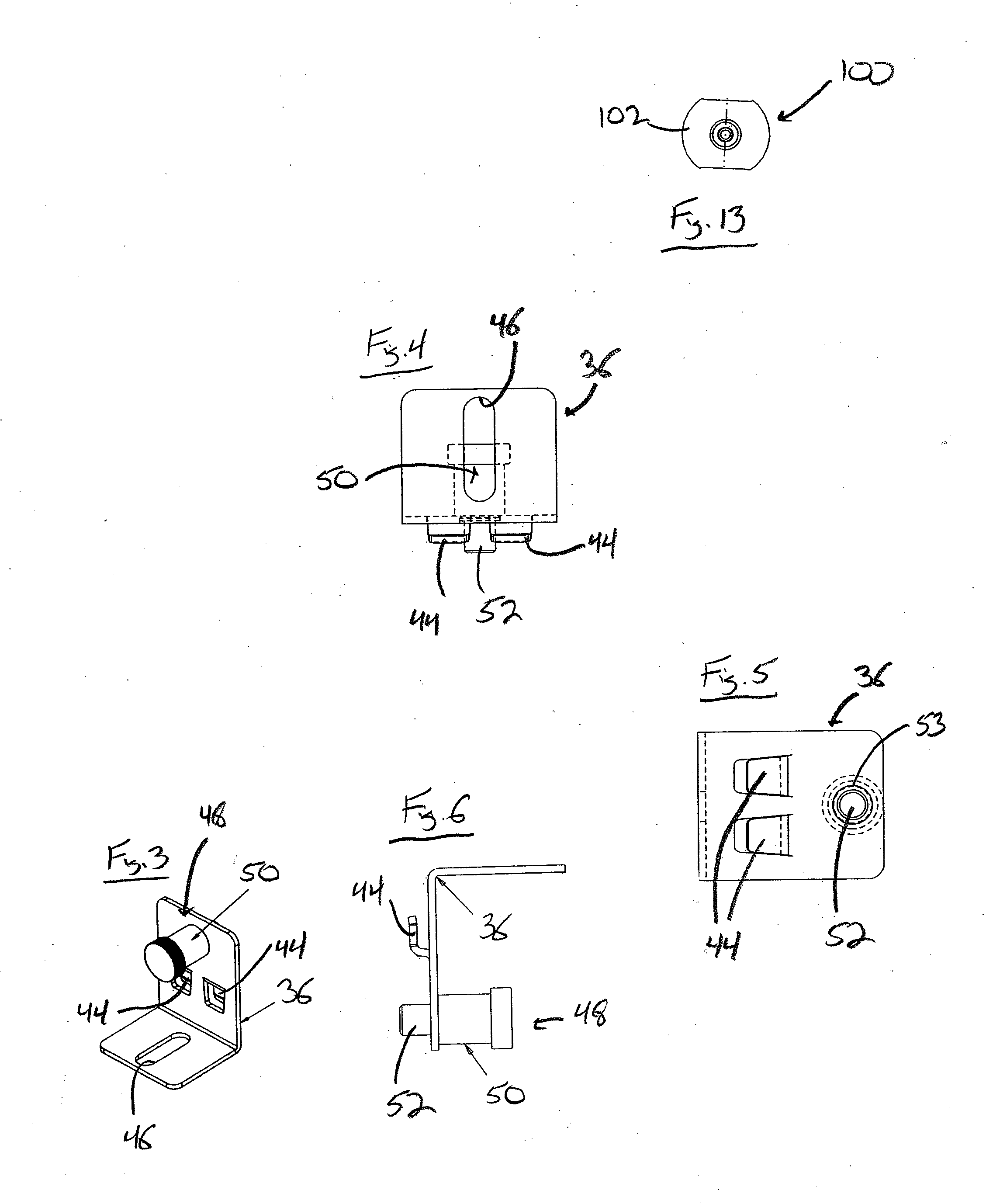
[0006]According to one aspect of the present invention, a bracket assembly includes a first mounting bracket attachable to a device, such as a power strip, is provided to enable the power strip to be releasably and easily connected to the frame of an enclosure to position the device where desired within the enclosure. The first mounting bracket includes a pair of engaging members that are adapted to be positioned within corresponding apertures in the enclosure frame to hold the power strip in the desired location. Adjacent to the engaging members, the first mounting bracket includes a locking mechanism that securely engages the first mounting bracket with the enclosure frame until such time as the mechanism is disengaged to enable the engaging members to be removed from the enclosure frame. The locking mechanism has a simple construction allowing the mechanism to be disengaged with one hand. This enables the first mounting bracket to which the power strip is secured to be disengaged, moved within the enclosure, and reengaged with the enclosure frame in a quick and easy manner.
[0009]According to still a further aspect of the present invention, the attachment of the first and second mounting brackets to the power strip allows the power strip to be spaced from the hanging bracket in a manner that enable the power strips to be rotated with regard to the mounting and hanging brackets, as well as with regard to the enclosure frame.

Problems solved by technology

While the enclosures can include a number of different arrangements of power outlets to provide a ready power supply to items contained in enclosures of this type, those outlets are not movable within the enclosure to accommodate different mounting configurations for components in the enclosure.

Method used


Image

  • Quick Release Power Strip Bracket assembly
  • Quick Release Power Strip Bracket assembly
  • Quick Release Power Strip Bracket assembly

Examples


Embodiment Construction

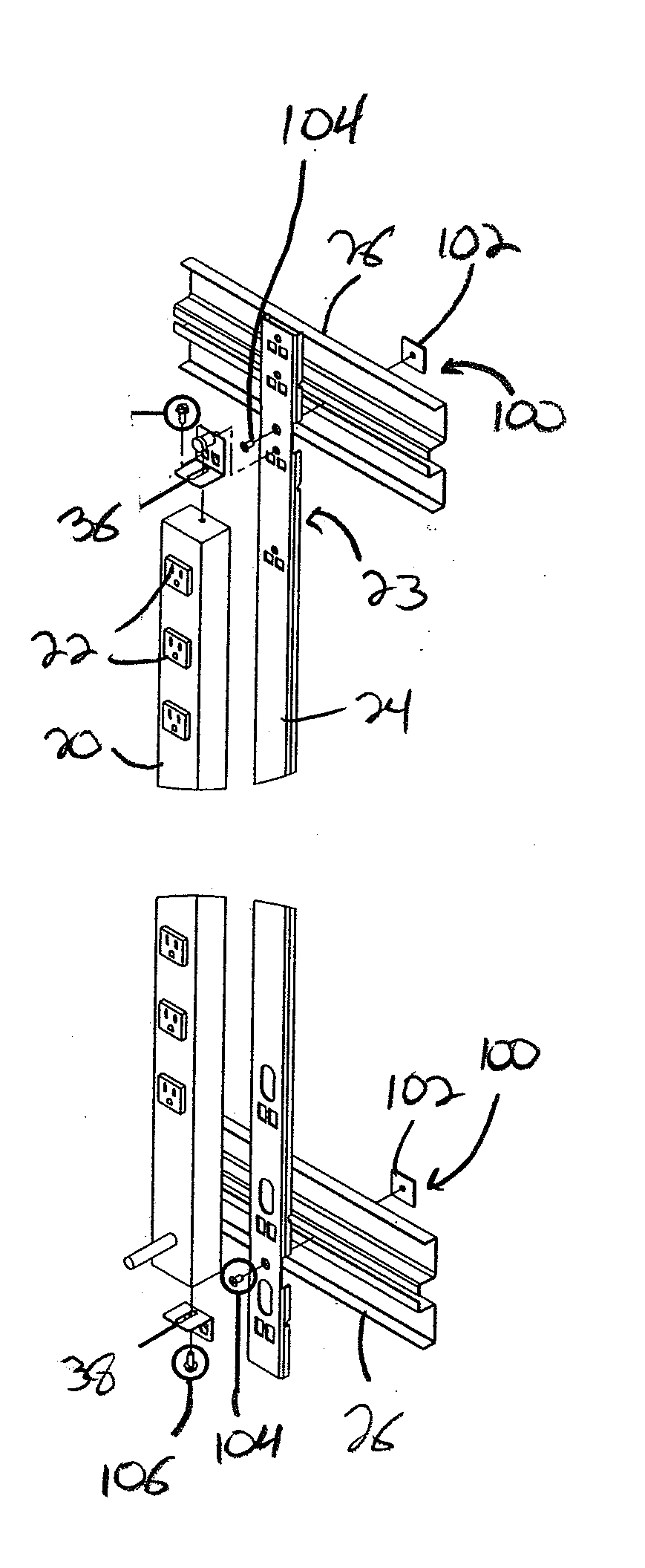
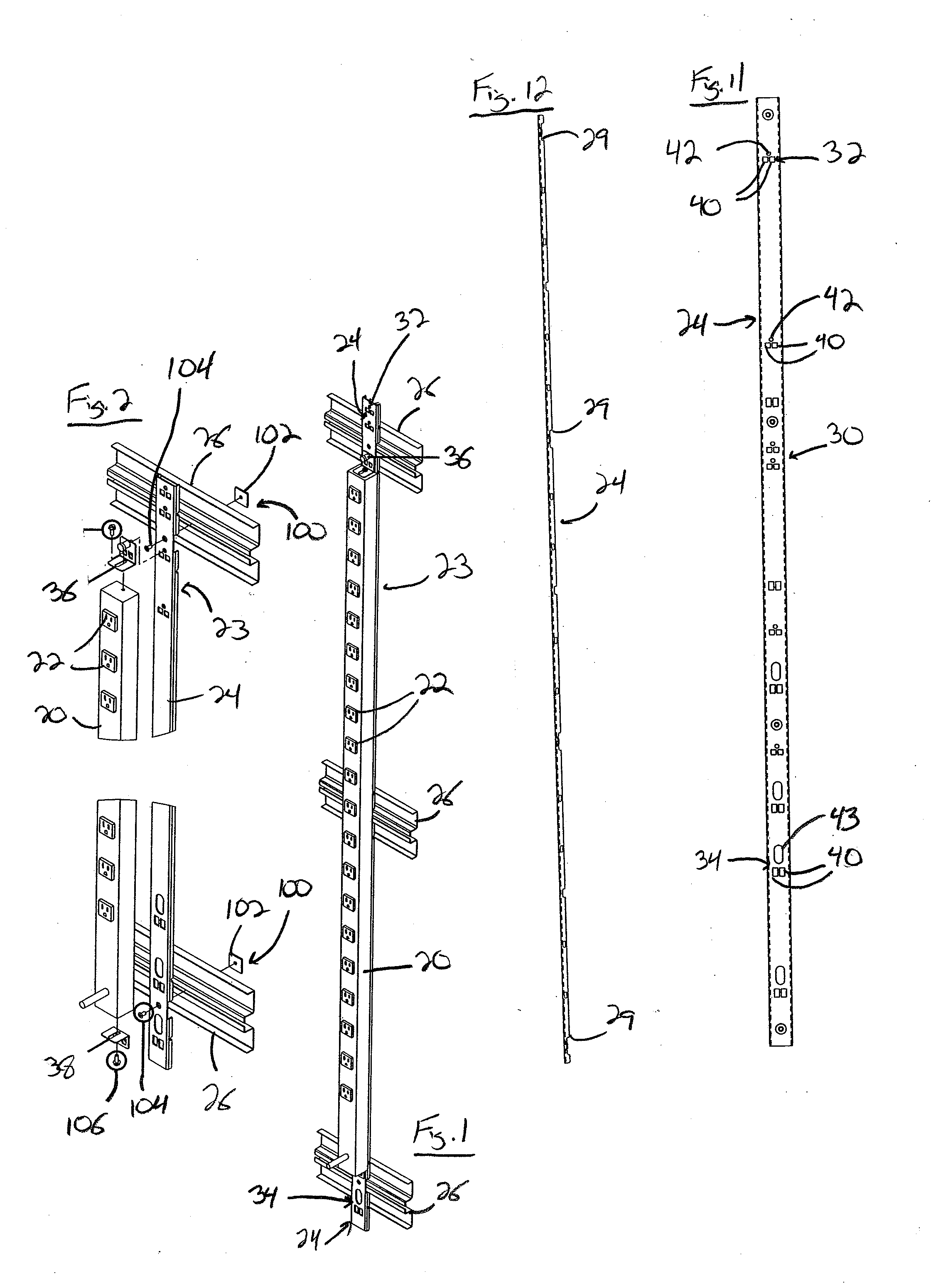
[0026]With reference now to the drawing figures in which like reference numerals designate like parts throughout the disclosure, a power strip adapted to be utilized with the present invention is indicated generally at 20 in FIGS. 1 and 2. The power strip 20 includes a number of outlets 22 spaced thereon for receiving a plug (not shown) that is operably connected to a piece of electrical or computer equipment (not shown) in order to supply power to the equipment via the plug.

[0027]The power strip 20 is releasably positionable on a bracket assembly 23 that includes a hanging bracket 24 that can be secured to the frame 26 of an enclosure 28 for the equipment. As best shown in FIGS. 11 and 12, the hanging bracket 24 is formed as an elongated member, preferably as a rigid material, such as a metal, that includes a number of recesses 29 formed therein that accommodate the components of the frame 26, and a number of sets of mounting apertures 30 spaced there along. Each set of apertures 3...


PUM


Abstract

A quick release bracket assembly is provided for securely attaching power strips and other devices to the interior of an enclosure used for housing electronic equipment. The assembly includes a hanging bracket disposed on the frame of the interior of the enclosure and including a number of apertures to which are attachable a pair of mounting brackets movably secured at opposite ends to a power strip. One of the mounting brackets includes a locking mechanism that is easily disengageable from one of a number of separate locking apertures formed within the hanging bracket in order to allow the power strip to be engaged and disengaged from the hanging bracket for repositioning of the power strip to accommodate various electrical components within the enclosure.

Description

CROSS-REFERENCE TO RELATED APPLICATIONS[0001]This application claims priority from U.S. Provisional Patent Application Ser. No. 60 / 793,507, filed on Apr. 20, 2006, the entirety of which is incorporated by reference herein.FIELD OF THE INVENTION[0002]The present invention relates generally to power outlets, and more specifically to a quick release bracket assembly attachable to a power strip to releasably and securely support the strip within a frame or cabinet.BACKGROUND OF THE INVENTION[0003]In order to compactly and easily store a number of electronic components, such as information technology equipment, a number of different types of structures and enclosures have been developed specifically for retaining these types of items. The enclosures are formed with a number of walls forming the exterior of the enclosure and a movable door allowing access to the interior of the enclosure. The walls include a number of mounting structures to enable the equipment to be secured within the en...

Claims


Application Information

Patent Timeline
Patent Type & Authority Applications(United States)
IPC IPC(8): A47B96/06
CPCA47B96/06A47B2220/0077A47B96/068H01R25/006
Inventor TAGGETT, BRAD
Owner MAYVILLE PROD
Learn More