Illuminator and Manufacturing Method

a manufacturing method and technology for leds, applied in the field of leds, can solve the problems of affecting the performance and reliability of leds, and difficult to achieve a uniform depth or thickness of polymer over the metal

Inactive Publication Date: 2007-11-08
EPI LIGHT
View PDF14 Cites 43 Cited by
  • Summary
  • Abstract
  • Description
  • Claims
  • Application Information

AI Technical Summary

Benefits of technology

[0042] In a further embodiment, the metal blanket is abraded at rai...

Problems solved by technology

Packaging a large numbers of LEDs within close proximity generates large amounts of heat.
This heat must be removed as it can have a deleterious effect on the performance and reliability of the LEDs.
Combining the above requirements for an efficient LED optical array package poses a major technical challenge.
However, while the polymer is a good electrical in...

Method used


Image

  • Illuminator and Manufacturing Method
  • Illuminator and Manufacturing Method
  • Illuminator and Manufacturing Method

Examples


Embodiment Construction

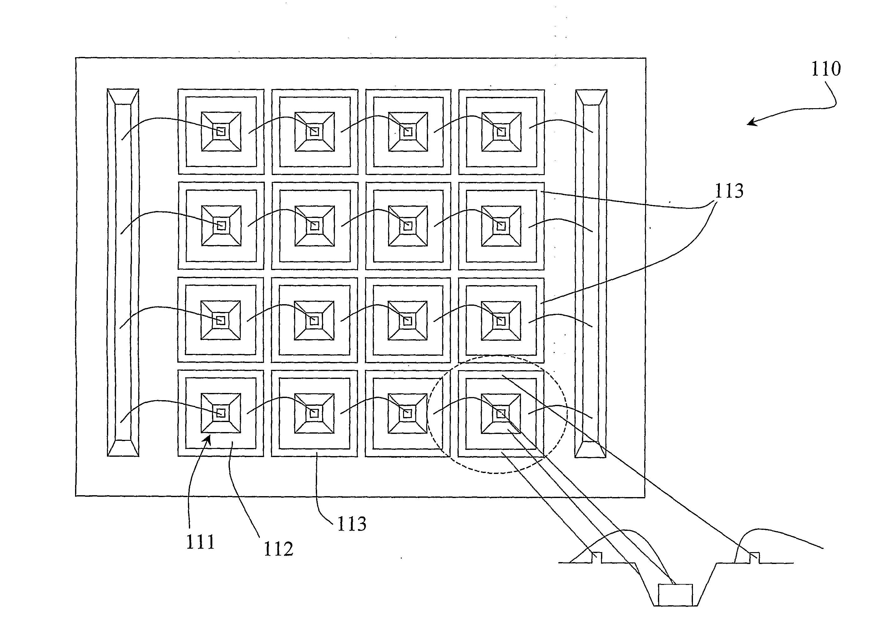
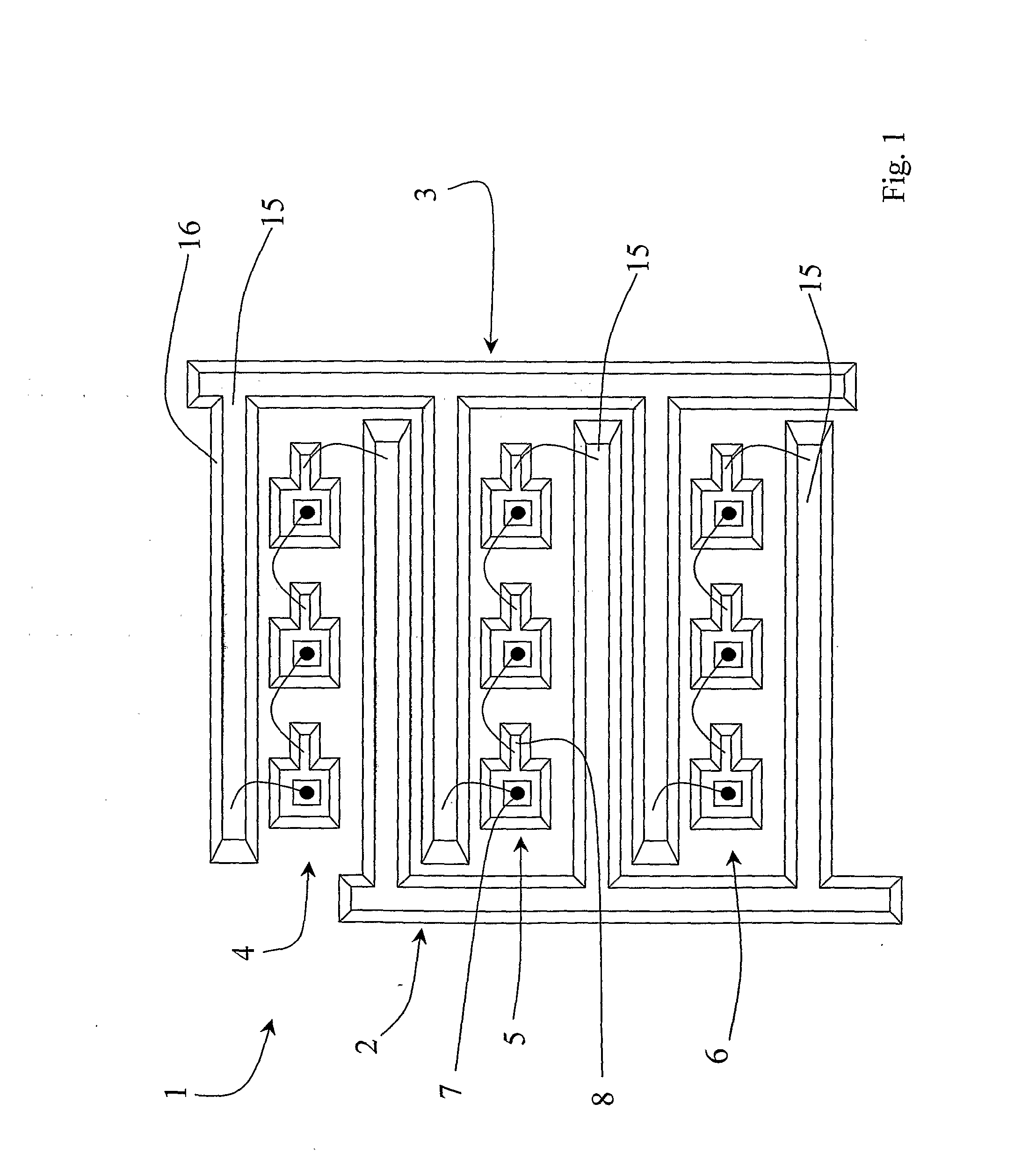
[0064] Referring to FIG. 1 an illuminator 1 comprises a substrate having electrically isolated recessed ground and power rails 2 and 3 across which are three series 4, 5, and 6 of bare die diodes in cavities. Each series comprises three LEDs 7, for each of which there is a recessed metal contact 8. Each end LED is wire-bonded to a rail 2 or 3. Each rail 2, 3 comprises a conductor 15 in a recess, and substrate side walls 16.

[0065] In this embodiment the substrate base is bulk aluminium. However, it may alternatively be of a different bulk material (such as copper) coated with aluminium. In this alternative embodiment, the illuminator would benefit from the higher thermal conductivity of copper, and it would be simple to bond the aluminium layer to the copper underneath.

[0066] The electrical isolator regions are part of an anodisation layer over the aluminium surface. The electrical conductor regions in the cavities and rails are part of a metal coating over the anodisation. The ano...


PUM


Abstract

An illuminator (1) is manufactured by embossing an aluminium preform to provide a structured substrate base (21) with cavities (25) for LEDs and recesses (26) for tracks. The substrate is anodised to provide an aluminium oxide insulating layer (30) over the structured surface. A metal layer (35) is then applied over the insulating layer (30), and this is etched to leave metal pads in the cavities and tracks in the recesses (26). LEDs (50) are placed in the cavities and they are wire-bonded to the exposed metal tracks. This manufacturing method allows versatility in choice of configuration of 5 illuminator by simple embossing a desired substrate shape. Also, the anodisation provides an excellent and durable insulating layer, which has the major benefit of being conformal with the structured surface.

Description

FIELD OF THE INVENTION [0001] The invention relates to illuminators and to their manufacture Prior Art Discussion [0002] High brightness LED arrays are required for a broad range of applications. These include general illumination (incandescent lamp replacement), illumination for machine vision, radiation induced curing of materials or epoxies (ultra-violet curing), and illumination for biosensing and medical therapies. High brightness is achieved by placing large numbers of LED chips in close proximity on an optical sub-mount or package. An optical package should serve the three important functions of providing an electrical contact, providing an optical reflector, and efficiently dissipating heat generated by the LEDs. [0003] Electrical connection of large numbers of LEDs in close proximity is often achieved by implementing a series-parallel circuit configuration. In this configuration, a number of LEDs are connected in series to form a chain and a number of chains are then connec...

Claims


Application Information

Patent Timeline
IPC IPC(8): H01L21/98H01L21/00F21K99/00
CPCG01N2201/062H01L33/60H01L2224/45015H01L24/45H01L2224/48091H01L2224/45144H05K2203/0315H05K1/053H05K1/183H05K3/045H05K3/107H05K2201/10106H01L2924/00014H01L2924/20752H01L2224/85205H01L2224/45H01L2924/00
Inventor O'BRIEN, PETER
Owner EPI LIGHT
Why Eureka
Try Eureka