
Vehicle bumper beam constructed of metal and plastic

a technology of metal and plastic, applied in the direction of bumpers, vehicle components, vehicular safety arrangments, etc., can solve the problems of not having good bending strength in a forward direction, metal components are unable to function as bumper reinforcement beams by themselves, etc., and achieve the effect of increasing strength

Inactive Publication Date: 2007-11-08
SHAPE CORP
View PDF2 Cites 44 Cited by
  • Summary
  • Abstract
  • Description
  • Claims
  • Application Information

AI Technical Summary

Benefits of technology

[0007] Another aspect of the present invention is to provide a bumper system for a vehicle comprising a first component and a second component. The first component has a length and opposing ends adapted for attachment to frame rails of a vehicle frame. The second component engages a face of the first component and is rigidly attached to the first component to form a structural beam with the stamped component. The second component is molded from material comprising a polymer and has energy-absorbing cells configured to crush and absorb energy upon a vehicle impact, whereby a need for a separate energy absorber on a face of the structural beam is substantially avoided.
[0009] Another aspect of the present invention is to provide a method of making a bumper system. The method includes forming a first component of a first material and forming a second component of a second material, with the first material and the second material being different. The method also includes engaging the second component with a face of the first component and rigidly attaching the second component to the first component in at least several locations along the length to form a structural beam with the first component. The method further includes providing the second component with sufficient structure to form an integral part of the structural beam but also having interconnected walls extending in the width direction to form energy-absorbing cells configured to crush and absorb energy upon a vehicle impact.
[0018] Another aspect of the present invention is to provide a bumper system for a passenger vehicle comprising a stamped metal component with coplanar mounting surfaces configured and adapted for attachment to frame rails of a vehicle frame; and an injection-molded component comprising a polymer engaging a face of the metal component; the injection-molded and metal components including front and rear walls that are fixedly secured together along top and bottom edges to form a unitary beam sufficient in length to extend between the rails; and the injection-molded component further having integrally-formed portions that fit at least partially into the stamped metal component for providing additional strength to the beam along predetermined longitudinal sections of the beam.
[0022] Another aspect of the present invention is to provide a bumper system for a passenger vehicle comprising a stamped metal component with coplanar mounting surfaces configured and adapted for attachment to frame rails of a vehicle frame; and an injection-molded component comprising a polymer engaging a face of the metal component; the injection-molded and metal components including front and rear walls, respectively, with top and bottom edges that overlap and that are fixedly secured together to form a unitary beam sufficient in length to extend between the rails; the top and bottom edges of the injection-molded component capturing the top and bottom edges of the metal component so that upon impact, the top and bottom edges of the metal component are captured and cannot spread, such that the unitary beam thus formed has an increased strength resisting premature kinking and collapse during impact.

Problems solved by technology

The metal component characteristically not having good bending strength in a forward direction as a stand-alone component due to a relatively flat geometry of the metal component, such that the metal component is unable to function as a bumper reinforcement beam by itself.

Method used


Image

  • Vehicle bumper beam constructed of metal and plastic
  • Vehicle bumper beam constructed of metal and plastic
  • Vehicle bumper beam constructed of metal and plastic

Examples


Embodiment Construction

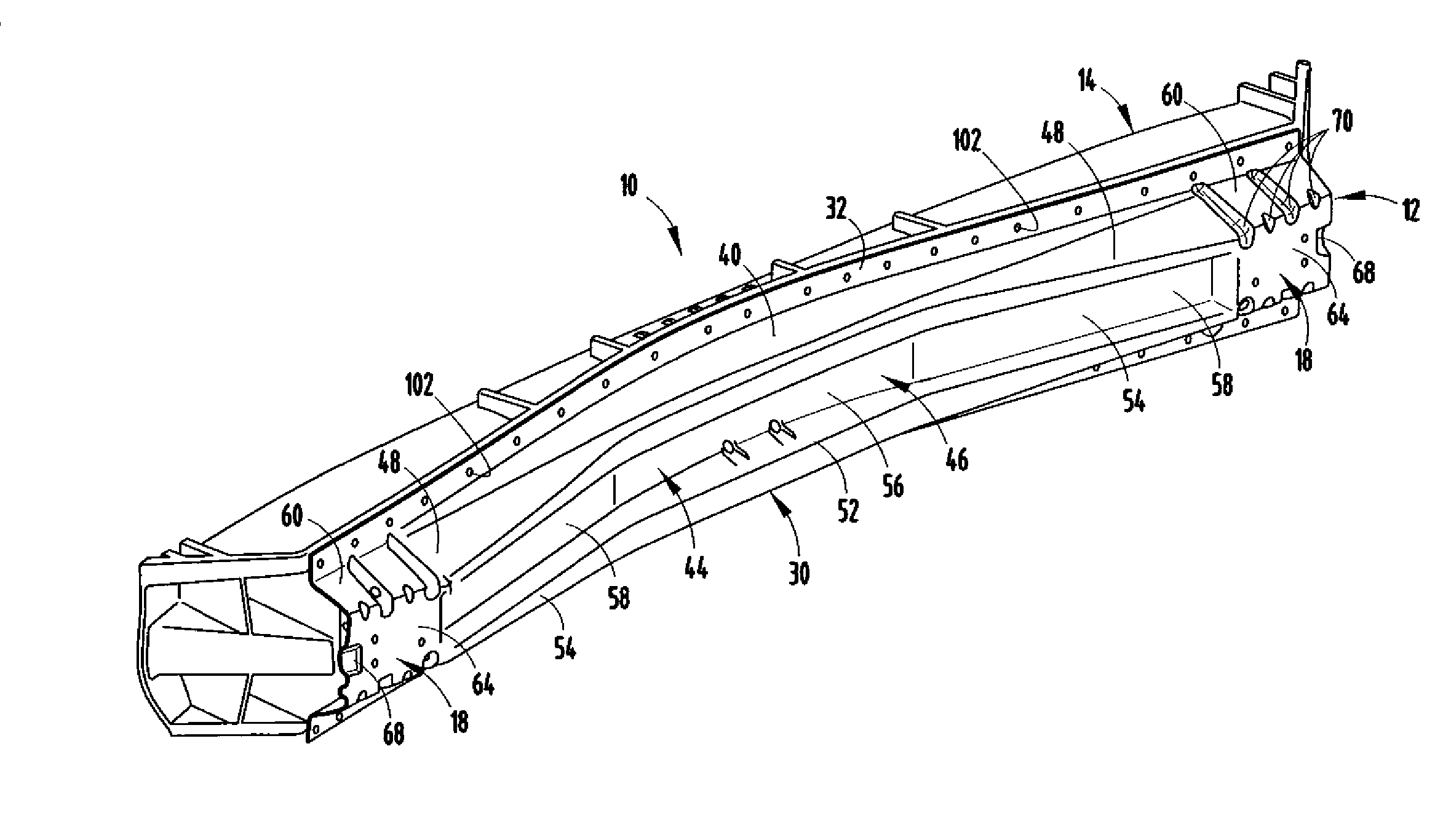
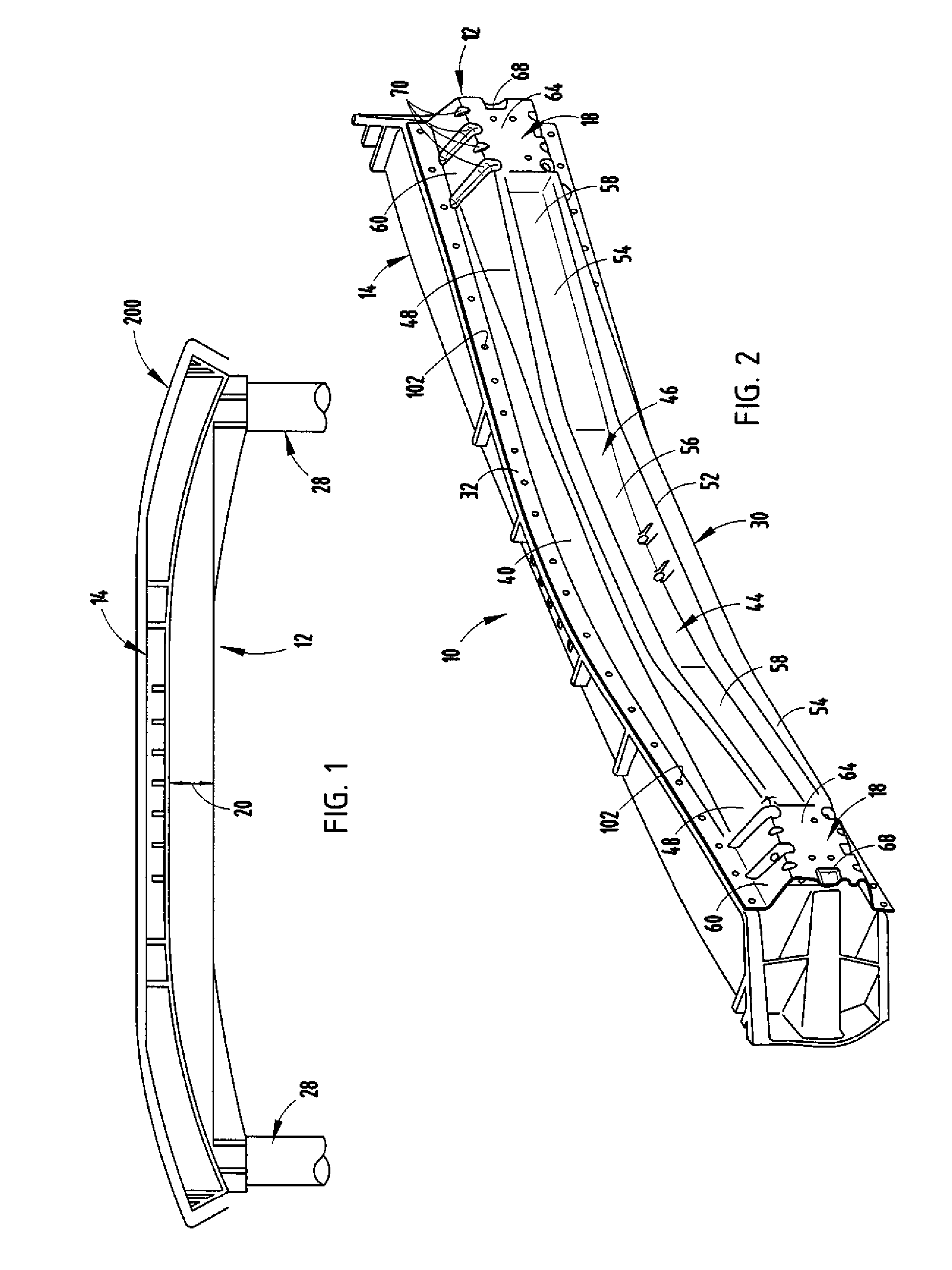
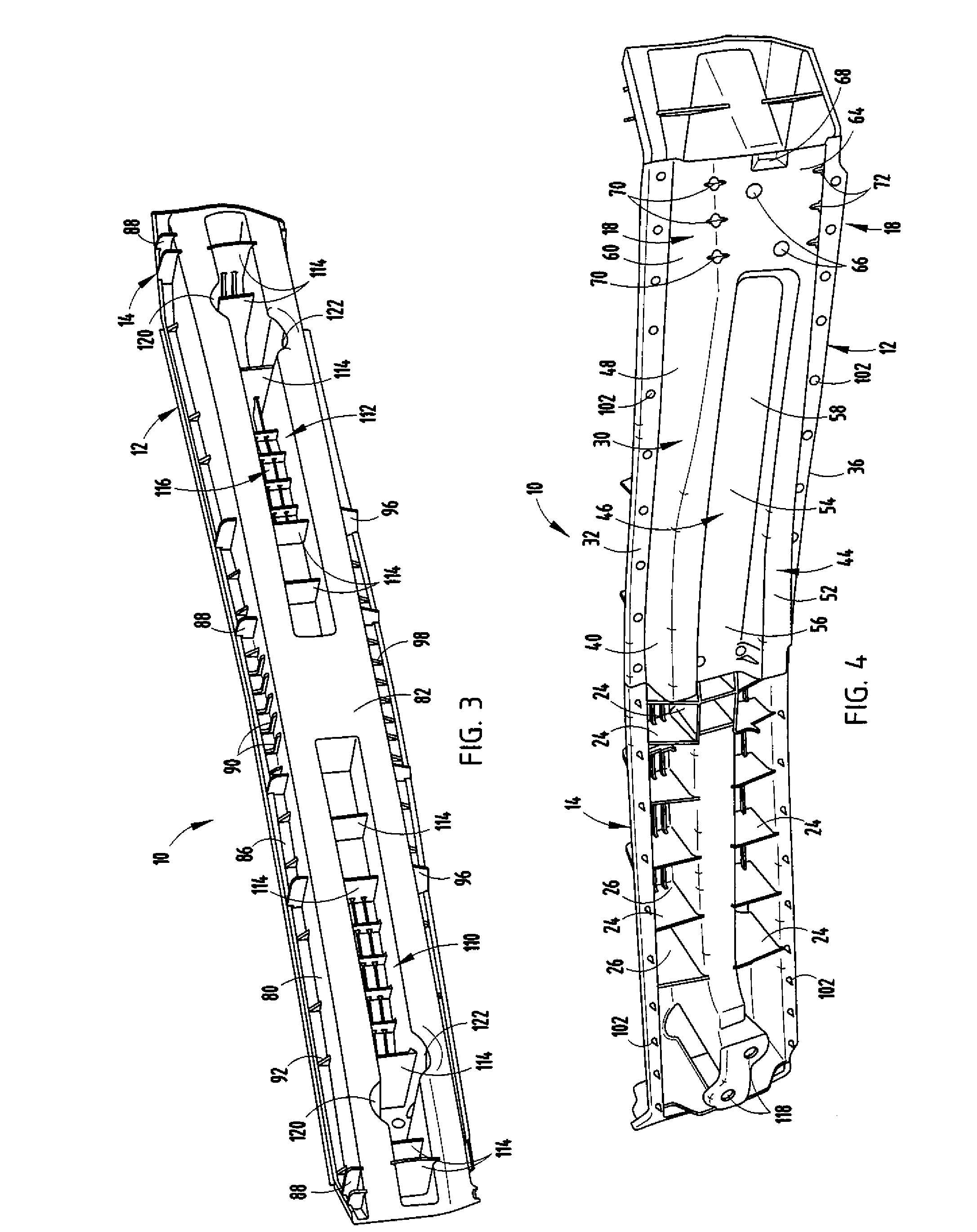
[0036] For purposes of description herein, the terms “upper,”“lower,”“right,”“left,”“rear,”“front,”“vertical,”“horizontal,” and derivatives thereof shall relate to the invention as orientated in FIG. 1. However, it is to be understood that the invention may assume various alternative orientations. In particular, the words “front” and “rear” are intended to be used herein for convenience and for understandability in the present description and claims, but it is intended that these terms are to be interpreted to be equally applicable to bumper systems used on a forward end or a rearward end of a vehicle. It is also to be understood that the specific devices and processes illustrated in the attached drawings, and described in the following specification are simply exemplary embodiments of the inventive concepts defined in the appended claims. Hence, specific dimensions and other physical characteristics relating to the embodiments disclosed herein are not to be considered as limiting, ...


PUM


Abstract

A bumper system for a vehicle comprising a stamped metal component and a second polymeric component fixedly attached to form a beam with particular localized energy absorber characteristics. The metal component is formed from a sheet and has a thickness in a width direction along a majority of the length when in a vehicle-mounted position. The second polymeric component engages a face of the first component and is rigidly attached to the first component in at least several locations along the length to form a structural beam with the first component. The second polymeric component has sufficient structure to form an integral part of the structural beam and interconnected walls extending in the width direction to form energy-absorbing cells at centered and corner locations configured to crush and absorb energy upon a vehicle impact.

Description

CROSS-REFERENCE TO RELATED APPLICATION [0001] This application claims priority to U.S. Provisional Patent Application No. 60 / 754,079 entitled VEHICLE BUMPER BEAM CONSTRUCTED OF METAL AND PLASTIC, which was filed on Dec. 27, 2005.BACKGROUND [0002] The present invention relates to a beam design that absorbs energy efficiently while deforming during an impact. Applications for this invention could include vehicle bumper systems, side impact bars, instrument panel cross-car substructures, and sill plates. [0003] Modern impact beams are designed to absorb a maximum of impact energy over a given stroke. At the same time, they are designed to minimize load spikes, and to distribute energy in a manner promoting uniform and predictable collapse upon undergoing loading from impact. Further, the individual components of an energy absorbing system must combine well with other energy absorbing components. [0004] In particular, improvements are desired to better integrate components of bumper sys...

Claims


Application Information

Patent Timeline
IPC IPC(8): B60R19/03
CPCB60R19/18B60R2019/1866B60R2019/1826
Inventor HEATHERINGTON, DAVID W.GLASGOW, SCOTT C.LYONS, BRUCE W.EVANS, DARIN
Owner SHAPE CORP
Learn More