Color EL display system with improved resolution

a display system and color el technology, applied in the field of color electroluminescent (el) display system devices, can solve the problems of limited addressability of most flat-panel displays, limited apparent resolution of the display, and inability of human visual systems to resolve further changes in physical resolution, etc., to achieve the effect of improving apparent resolution, reducing power consumption, and prolonging li

Inactive Publication Date: 2007-11-08
GLOBAL OLED TECH
View PDF18 Cites 25 Cited by
  • Summary
  • Abstract
  • Description
  • Claims
  • Application Information

AI Technical Summary

Benefits of technology

[0017] The advantages of various embodiment of this invention include providing a color display syst

Problems solved by technology

The first of these occur when the physical resolution of the display device is small enough that the human visual system is unable to resolve further changes in physical resolution (i.e., the apparent resolution of the display becomes eye-limited).
Addressability in most flat-panel displays, especially active-matrix displays, is limited by the need to provide signal busses and electronic control elements in the display.
Further, in such display devices, as the light-emitting area is decreased, the current density required across the EL stack to produce a desired luminance increases and this increase in current density is known to reduce the lifetime of the display device.
Regardless of whether the area required for patterning busses and control elements compete with the light-emitting area of the display, the decrease in bus and control element size that occur with increases in addressability for a given display generally require more accurate, and therefore more complex, manufacturing processes and can result in greater number of defective panels, decreasing yield rate and increasing the cost of marketable displays.
This

Method used


Image

  • Color EL display system with improved resolution
  • Color EL display system with improved resolution
  • Color EL display system with improved resolution

Examples


Embodiment Construction

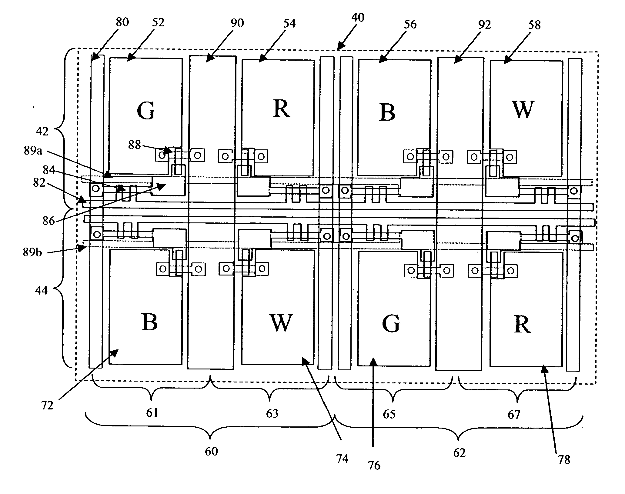
[0028] Referring to FIG. 5, full color electro-luminescent display systems in accordance with the invention are comprised of a display device 142 and a controller 140. Referring to FIG. 3, the display device is comprised of a plurality of red 54, 78, green 52, 76, and blue 56, 72 light-emitting elements, and at least one additional 58, 74 color of light-emitting element having luminance efficiency greater than at least one of the red, green and blue light-emitting elements and preferably a luminance efficiency that is greater than the average efficiencies of the red, green and blue light-emitting elements. Referring to FIG. 4, each light-emitting element includes a first electrode 96 and a second electrode 130 having one or more electro-luminescent layers 110 formed there-between, at least one electro-luminescent layer being light-emitting, at least one of the electrodes being transparent and wherein the first and second electrodes defining one or more light-emissive areas. Within t...


PUM


Abstract

A full color electro-luminescent display system, comprising: a display device comprised of a plurality of red, green, blue light-emitting elements and at least one additional color of light-emitting element having luminance efficiency greater than at least one of the red, green and blue light-emitting elements, wherein the light-emitting elements are laid out over a substrate in adjacent columns arranged along a first dimension and adjacent rows arranged along a second dimension, such that each pair of adjacent columns of light-emitting elements, and each row of light-emitting elements, contain each of the red, green, blue and additional color light-emitting elements; and a controller for receiving an input signal for an input image having a two-dimensional spatial content including edge boundaries between first and second regions of the input image and driving the display, the controller being responsive to the two-dimensional spatial content of the input image and increasing apparent display resolution while providing increased display power efficiency.

Description

FIELD OF THE INVENTION [0001] The present invention relates to color electro-luminescent (EL) display system devices and, more particularly, to arrangements of light-emitting elements and electrical layouts in such color display system devices. BACKGROUND OF THE INVENTION [0002] Flat panel, color displays for displaying information, including images, text, and graphics are widely used. These displays may employ any number of known technologies, including liquid crystal light modulators, plasma emission, electro-luminescence (including organic light-emitting diodes), and field emission. Such displays include entertainment devices such as televisions, monitors for interacting with computers, and displays employed in hand-held electronic devices such as cell phones, game consoles, and personal digital assistants. In these displays, the resolution of the display is always a critical element in the performance and usefulness of the display. The resolution of the display specifies the qua...

Claims


Application Information

Patent Timeline
IPC IPC(8): G09G5/02
CPCG09G3/2003G09G3/3208G09G2340/06G09G2340/0457G09G2300/0452
Inventor MILLER, MICHAEL E.MURDOCH, MICHAEL J.COK, RONALD S.
Owner GLOBAL OLED TECH
Why Eureka
Try Eureka