Flexible laser safety curtain

Inactive Publication Date: 2007-11-08
TELESIS TECH
View PDF2 Cites 15 Cited by
  • Summary
  • Abstract
  • Description
  • Claims
  • Application Information

AI Technical Summary

Problems solved by technology

The lasers used in many of these devices and systems are often capable of producing energy output that is potentially harmful to both people and equipment.
Further, some forms of laser radiation can damage an unprotected human eye even before it has time to react to the exposure.
This may lead to considerable physical damage to the eye, such as cutting or burning, and can also result in temporary or permanent vision impairment or blindness.
At other focal lengths however, the laser radiation may be harmful even at large distances from the source.
Another potential danger associated with lasers is that of chemical vapors, dust or melted liquids that may be formed in the area where the laser interacts with a work surface, such as in laser welding or scribing.
The harmful properties of those chemicals may adversely affect nearby persons if inhaled or otherwise transferred to the body.
Class II systems are considered a hazard for direct long-term ocular exposure.
Class III system emission levels are ocular hazards for direct exposure and may be hazardous to skin at longer exposure times. Class IV systems are the most hazardous and pose a danger to eyes and skin upon direct, as well as indirect exposure

Method used


Image

  • Flexible laser safety curtain
  • Flexible laser safety curtain
  • Flexible laser safety curtain

Examples


Embodiment Construction

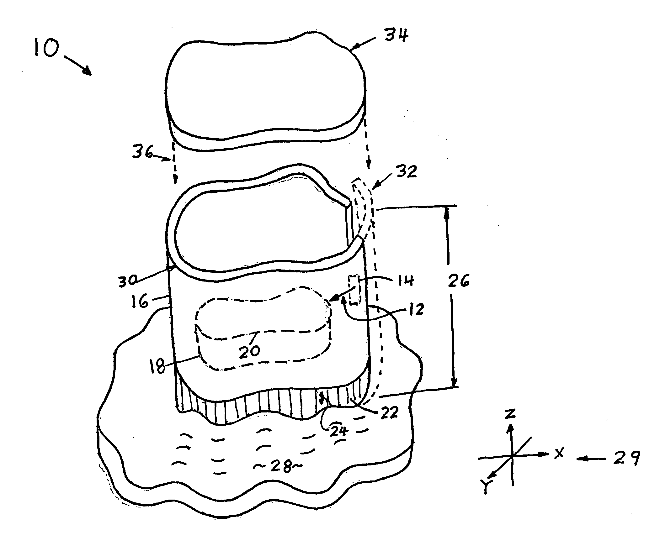
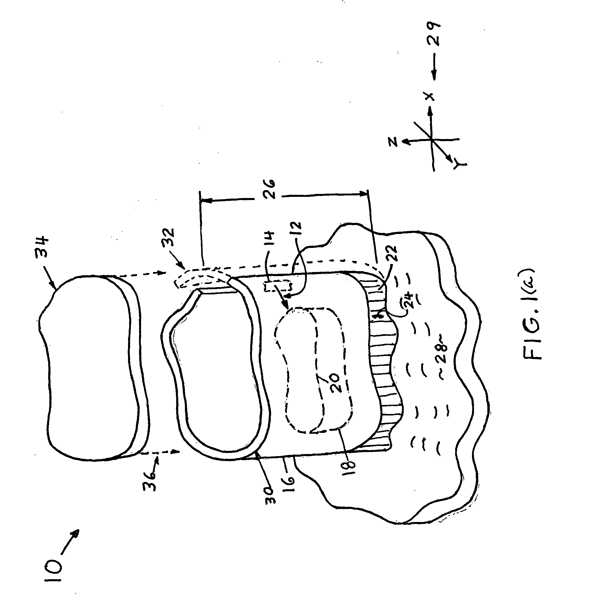
[0029] An embodiment of the present invention is illustrated generally in FIG. 1(a). A flexible shield 10 is shown for blocking laser radiation 12 from a laser source 14. The shield 10 is configured with a flexible wall portion 16 allowing the shield 10 to be positioned near an object 18 which may have an irregular contour (such as 20) upon which the laser beam 12 is to be applied. The shield 10 also has a flexible edge portion 22, providing resilience in a direction 24 parallel to the wall portion 16 length 26. The resilient flexibility of edge portion 22 is for conformance with an irregular surface such as surface 28 upon which the shield 10 is positioned. The surface 28 may or may not be a part of an object 18.

[0030] For purposes of description of the flexibility of the shield, FIG. 1(a) shows an xyz coordinate system 29 for defining terminology to be used herein relating to shield orientation. Movement of the shield as shown in FIG. 1(a) in a z direction will be referred to as ...


PUM

PropertyMeasurementUnit
Flexibilityaaaaaaaaaa

Abstract

A flexible laser safety curtain is disclosed that utilizes a plurality of columns flexibly attached to one another along their longitudinal edges in such a manner as to create a curtain of columns. The base of each column contains a cavity within which at least one moveable element, columnar in form, may be located and protrude from the cavity. The moveable element, when pressed against a work surface, is forced into the cavity. A biasing element within the cavity provides an opposite force on the moveable elements to both keep the moveable element in contact with the work surface, and to return the moveable element to its original position when the inward force is removed. The curtain's edge follows the contours of an uneven work surface and thereby the curtain provides a complete barrier to laser radiation.

Description

RELATED APPLICATIONS [0001] The present application claims priority from U.S. Provisional Patent application Ser. No. 60 / 797,258 filed May 02, 2006, which is incorporated herein by reference.BACKGROUND OF THE INVENTION [0002] 1. Field of the Invention [0003] The present invention relates generally to safety systems for lasers, and more particularly to a flexible laser safety shield that provides a flexibly adjustable barrier to laser radiation. [0004] 1. Brief Description of the Prior Art [0005] Many types of laser-based devices and systems, having a wide range of applications in fields such as manufacturing, research, communications and medicine have become increasingly well-known and commercially available. The lasers used in many of these devices and systems are often capable of producing energy output that is potentially harmful to both people and equipment. [0006] The potential dangers associated with lasers are several. For example, bums to the skin and clothing or even to nea...

Claims


Application Information

Patent Timeline
IPC IPC(8): H01S3/00
CPCB23K26/427F16P1/06F16P1/02B23K26/706
Inventor HARRISON, MICHAELFERRARIO, JOSEPHMESROPYAN, ASHOT
Owner TELESIS TECH
Why Eureka
Try Eureka