Pierce nut and use thereof

a nut and nut technology, applied in the direction of nuts, screws, bolts, etc., can solve the problems of increasing the risk of tool damage, increasing the load on the punching tool, increasing the wear and tear of the punching die, etc., and achieving the effect of reducing or eliminating the problems associated

Active Publication Date: 2007-11-08
STROMSHOLMEN
View PDF17 Cites 18 Cited by
  • Summary
  • Abstract
  • Description
  • Claims
  • Application Information

AI Technical Summary

Benefits of technology

[0012] An object is therefore to provide a pierce nut that elimina

Problems solved by technology

Other affected parameters whose importance increases are punching force, tool damage and nut centering; as the strength of the punched metal sheet increases, greater punching force is required, which increases the load on the punching tools as well as the risk of alignment errors occurring between the pierce nut and the punching die, thereby increasing the risk of tool damage.
The pierce nut disclosed in U.S. Pat. No. 5,340,251 requires substantial deformation of the metal sheet to push it under the undercut portions, which in connection with high-strength sheet metal increases the stress on the pilot of the pierce nut, necessitates great punching force and, thus, increases wear also on the punching die.
In addition, when using the pierce nut according to U.S.

Method used


Image

  • Pierce nut and use thereof
  • Pierce nut and use thereof
  • Pierce nut and use thereof

Examples


Embodiment Construction

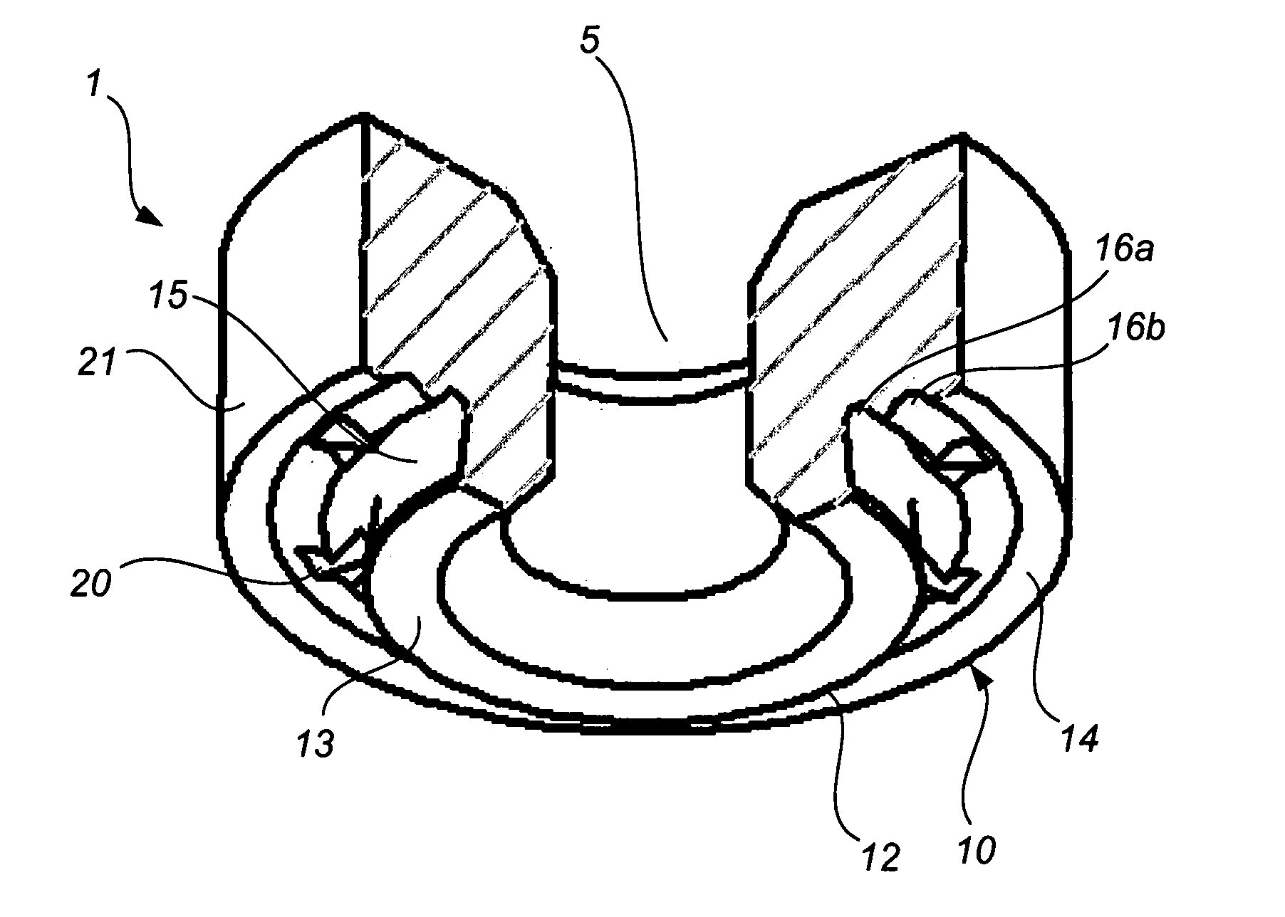
[0060] The pierce nut 1 is designed so as to punch its own hole during the punching operation and to push sheet material into grooves, undercuts etc. in the pierce nut during the operation.

[0061] Depending on the sheet thickness, there are different optimized geometries.

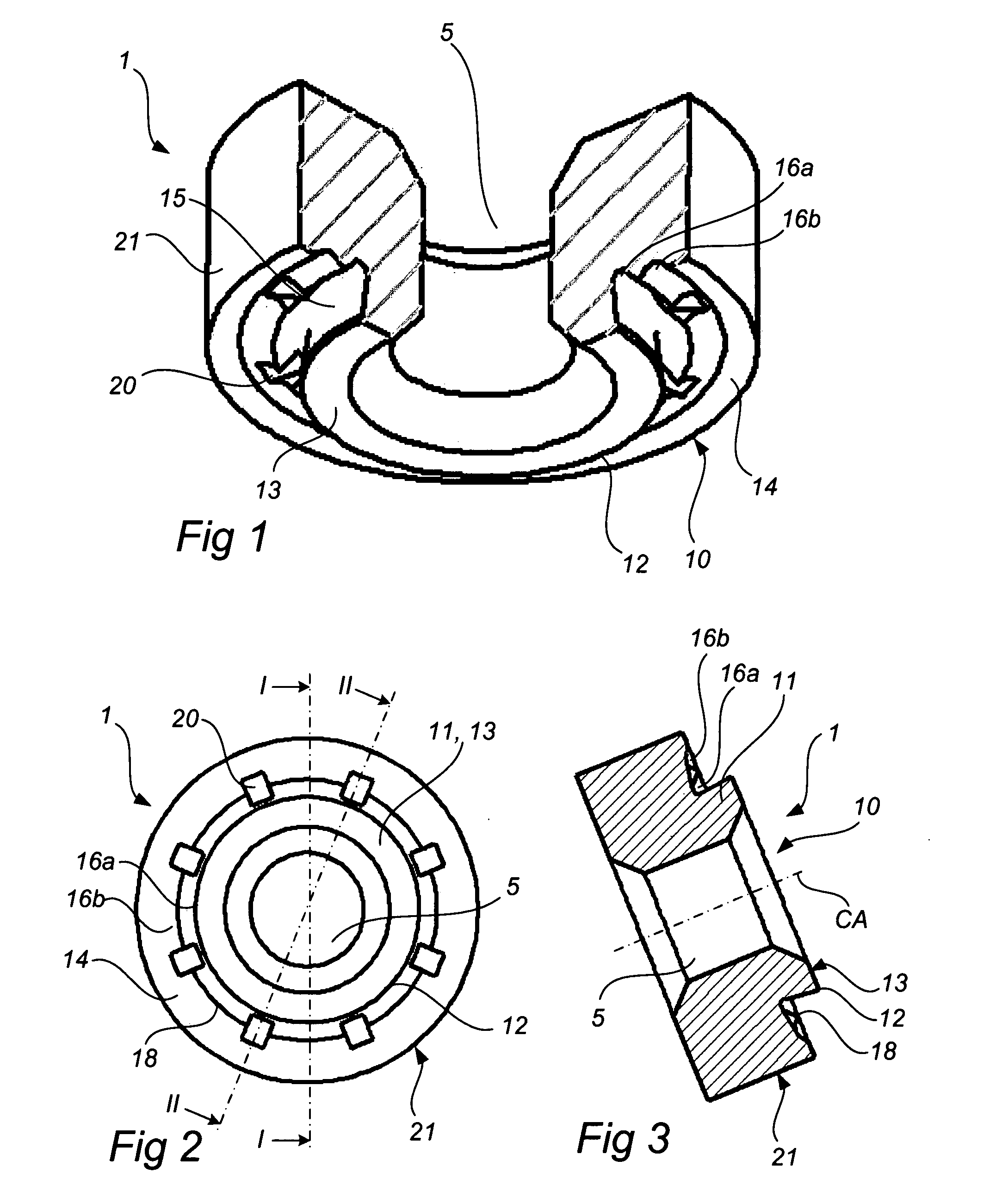
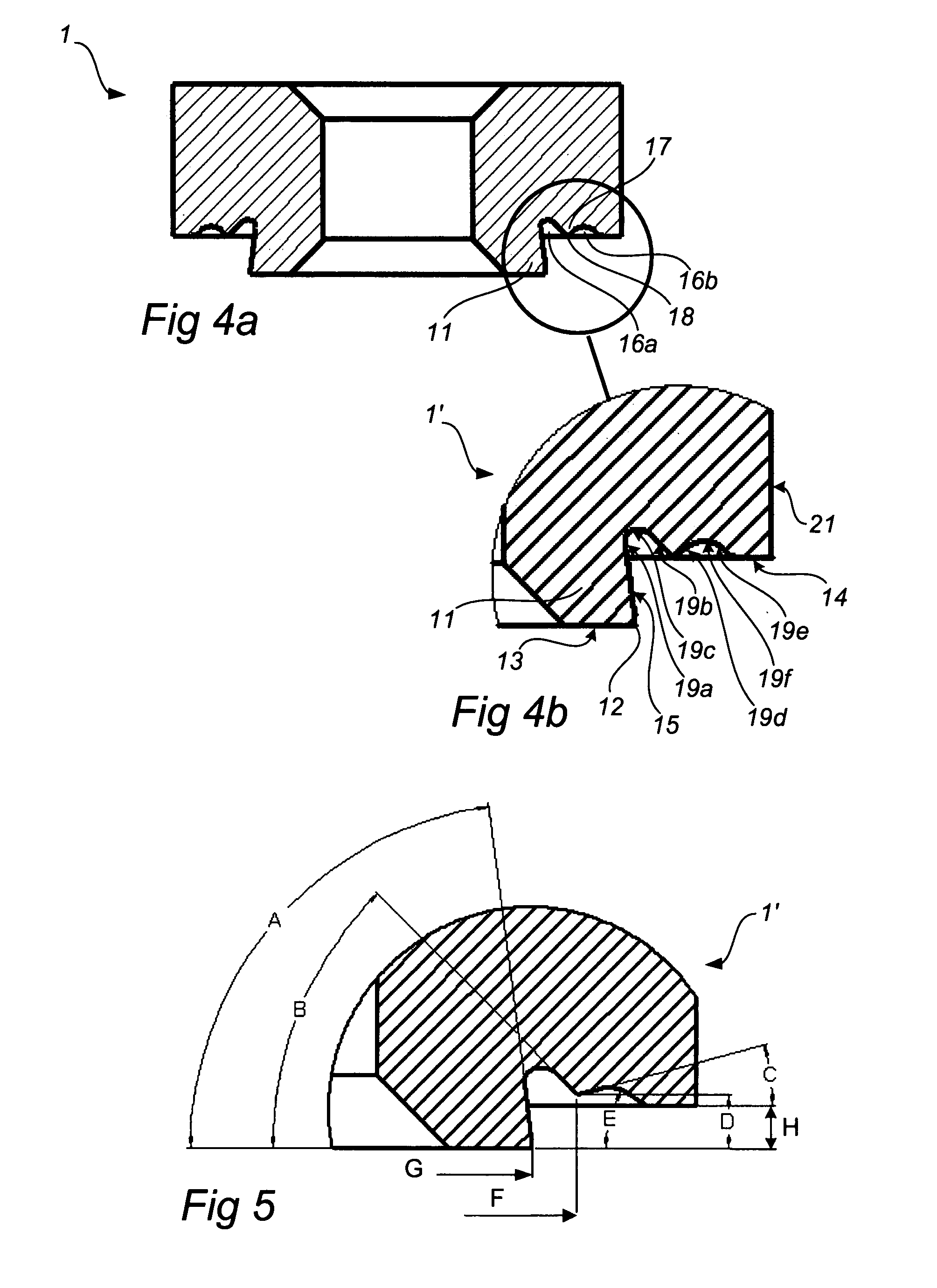
[0062] The pierce nut 1 has a centered, threaded through hole 5. On the underside of the pierce nut, in the following referred to as the engagement side 10, a pilot 11 protrudes. The protrusion H of the pilot 11 relatively to the end surface 14 of the other portion on the engagement side 10 depends primarily on the sheet thickness. Generally, the protrusion H is about 1.2 mm for sheet thicknesses up to about 1.3-1.6 mm and about 0.65 mm for sheet thicknesses up to about 0.7-1.2 mm.

[0063] The pilot 11 has a plane, annular end surface 13 with a punching edge 12 which engages a sheet 4 and a punching die 3 during the actual punching (FIGS. 6-8). Radially outside the pilot 11, an annular wall surface 15 is provided wh...


PUM

PropertyMeasurementUnit
Angleaaaaaaaaaa
Angleaaaaaaaaaa
Angleaaaaaaaaaa

Abstract

A pierce nut (1) for attachment to a plastically deformable metal sheet (4) has an abutment surface (14) adapted to abut against the metal sheet (4), an undercut pilot (11) protruding relatively to the abutment surface (14), and a countersunk groove (16a, 16b) which is formed in the abutment surface (14) and at least partly surrounds the pilot (11). The groove (16a, 16b) is without active undercuts facing the pilot (11). The groove comprises an inner groove (16a) and an outer groove (16b) and a ridge (17) located therebetween.

Description

[0001] The present invention claims priority on U.S. Provisional Patent Application Ser. No. 60 / 794,520 filed Apr. 25, 2006, which is incorporated herein. [0002] The present invention relates to a pierce nut and to the use of such a pierce nut. More specifically, the present invention concerns a pierce nut that is particularly suited for high-strength sheet metal.BACKGROUND OF THE INVENTION [0003] Pierce nuts have been used in mass production applications for many years. In the automotive industry, they are used to allow the mounting of components in metal sheets and panels. In general, to attach these components, threaded screws or bolts are used, and the joint can be tightened by means of a torque wrench. [0004] Previously, there was a general tendency in the automotive industry to use thin metal sheets and panels to reduce the weight of the vehicles. Thus, the focus was on the development of pierce nuts designed to provide high torque resistance and pull-through resistance, also ...

Claims


Application Information

Patent Timeline
IPC IPC(8): B23P11/00B23P17/00F16B39/00
CPCB23P19/062Y10T29/49835Y10T29/49947F16B37/068
Inventor GARDSTAM, JOHANNES
Owner STROMSHOLMEN
Why Eureka
Try Eureka