Optical Sensor and Methods of Making It

a technology of optical sensors and sensors, applied in the field of optical sensors, can solve the problems of degrading the performance of the sensors and contamination of the instruments, and achieve the effects of facilitating the movement of liquid samples, proper alignment of the sensors, and convenient handling for users

Inactive Publication Date: 2007-11-08
CHARLTON STEVEN C +3
View PDF9 Cites 20 Cited by
  • Summary
  • Abstract
  • Description
  • Claims
  • Application Information

AI Technical Summary

Benefits of technology

[0010] A sensor of the invention is used in optically measuring the analyte contained in a liquid biological sample, particularly the glucose content of whole blood. When inserted into a meter, one end of the sensor extends from the meter. Liquid samples are applied by the user to the accessible end of the sensor. The liquid sample travels by capillary action into the meter where it contacts reagents that provide an optical response to the analyte in the sample. That response is read by the meter and reported to the user. The reagents are contained in a thin layer deposited within the capillary channel. The sensor of the invention includes an air vent from the capillary channel located downstream of the reagents which facilitates the movement of the liquid sample into the meter by capillary action. A handling part or tab also extends outside the glucose meter, making it convenient for the user to handle the sensor, that is, inserting it into the meter and removing it after use. Calibration of the sensors is provided to the meter by a bar code on one side of the sensor or by a laser-marked conductive pad printed on the sensor, in either case, on a portion of the sensor that extends into the meter. Proper alignment of the sensor is assured by markings on the sensor and the meter and by tabs which engage recesses in the meter.
[0011] Sensors of the invention can be made by web-based processes that are capable of producing large numbers of sensors. A base stock is punched to provide traction holes and other features of the sensor. Then, the capillary channel is formed between adhesive strips applied to the base stock, the reagents are applied to the desired region of the capillary channel, a conductive pad is printed if desired, and finally a strip of clear or opaque stock is applied to complete the sensor. The characteristic properties of the sensor are then tested and appropriate calibration information is added, after which the individual sensors are cut from the base stock.

Problems solved by technology

However, handling individual sensors risks contamination of the instrument and degrading the performance of the sensors.

Method used


Image

  • Optical Sensor and Methods of Making It
  • Optical Sensor and Methods of Making It
  • Optical Sensor and Methods of Making It

Examples


embodiment b

[0050] Alternative Embodiment B

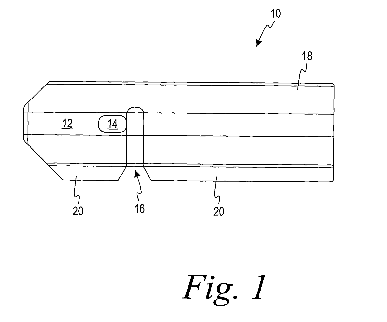
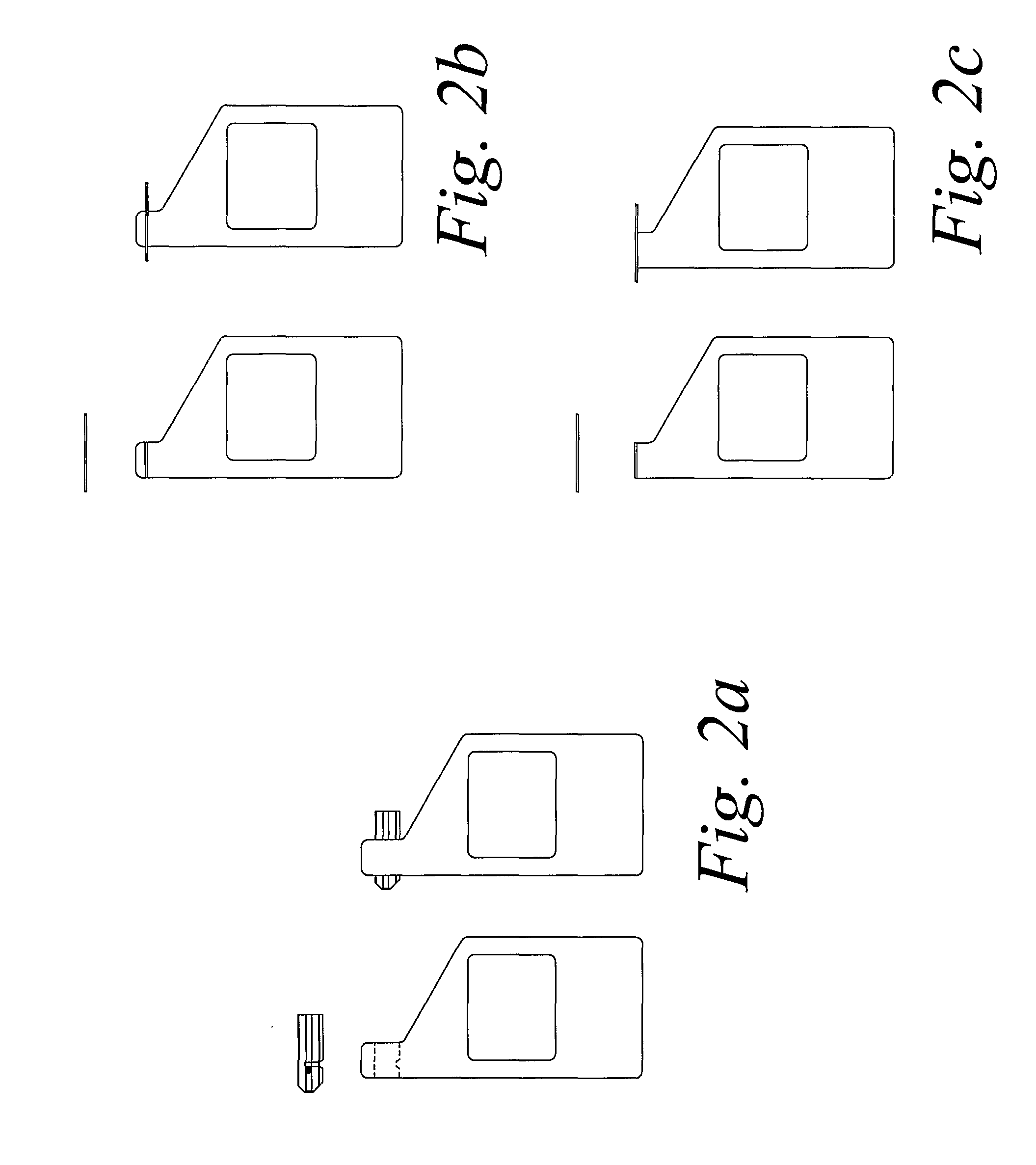
[0051] The sensor of embodiment A wherein said sensor is substantially flat and adapted to be inserted into a slot in said meter with portions of said capillary channel, said air vent and said handling area extending outwardly from said slot.

embodiment c

[0052] Alternative Embodiment C

[0053] The sensor of embodiment B wherein said sensor is substantially flat and in the shape of a snow-boot adapted to be inserted into a slot in said meter with portions of said capillary channel, said air vent and said handling area extending outwardly from said slot.

embodiment d

[0054] Alternative Embodiment D

[0055] The sensor of embodiment A wherein said sensor is substantially flat and adapted to be positioned adjacent said meter with portions of said capillary channel, said air vent and said handling area extending outwardly from said meter.

[0056] Alternative Embodiment E

[0057] The sensor of embodiment A wherein said means for providing encoded information is a bar code.


PUM

PropertyMeasurementUnit
volumeaaaaaaaaaa
optical responseaaaaaaaaaa
areaaaaaaaaaaa

Abstract

A sensor for optically measuring an analyte contained in a liquid biological sample, particularly measuring the glucose content of blood in a glucose meter. The sensor in a preferred embodiment takes the form of a snow-boot. That is, it has a top portion including an air vent and an area that the user grasps to insert and remove the sensor from the slot in a glucose meter. The bottom or toe region of the sensor extends from the glucose meter and provides the entrance to a capillary channel for introducing a sample of blood into the meter, where it contacts reagents providing an optical response. The optics within the meter read the optical response of the reagents and correlates it with the glucose content of the sample.

Description

CROSS-REFERENCE TO RELATED APPLICATION [0001] This application claims priority to U.S. Provisional Application No. 60 / 611,464, filed on Sep. 20, 2004.FIELD OF THE INVENTION [0002] This invention relates generally to the field of medical devices. More particularly to devices used by a patient, rather than a medical professional. BACKGROUND OF THE INVENTION [0003] The invention concerns analysis of biological samples, such as blood, urine and the like, carried out by an individual for determining the status of their body chemistry. Instruments have been developed to allow frequent testing at home or at other places without the need to submit samples to medical laboratories. For example, the invention concerns diabetic individuals who must test their blood frequently to determine the glucose content, so that their diet and medication can be adjusted. Although the invention will be described in relation to measuring glucose in blood, it has application to measuring other analytes such a...

Claims


Application Information

Patent Timeline
Patent Type & Authority Applications(United States)
IPC IPC(8): G01N33/66B01L11/00B05D5/12B01L99/00
CPCB01L3/5027B01L3/502715B01L3/502723B01L9/52G01N21/8483B01L2200/16B01L2300/0825B01L2300/0887B01L2400/0406B01L2200/025
Inventor CHARLTON, STEVEN C.HUANG, DIJIAGEORGE, SUNY J.JUNG, SUNG-KWON
Owner CHARLTON STEVEN C
Why Eureka
Try Eureka