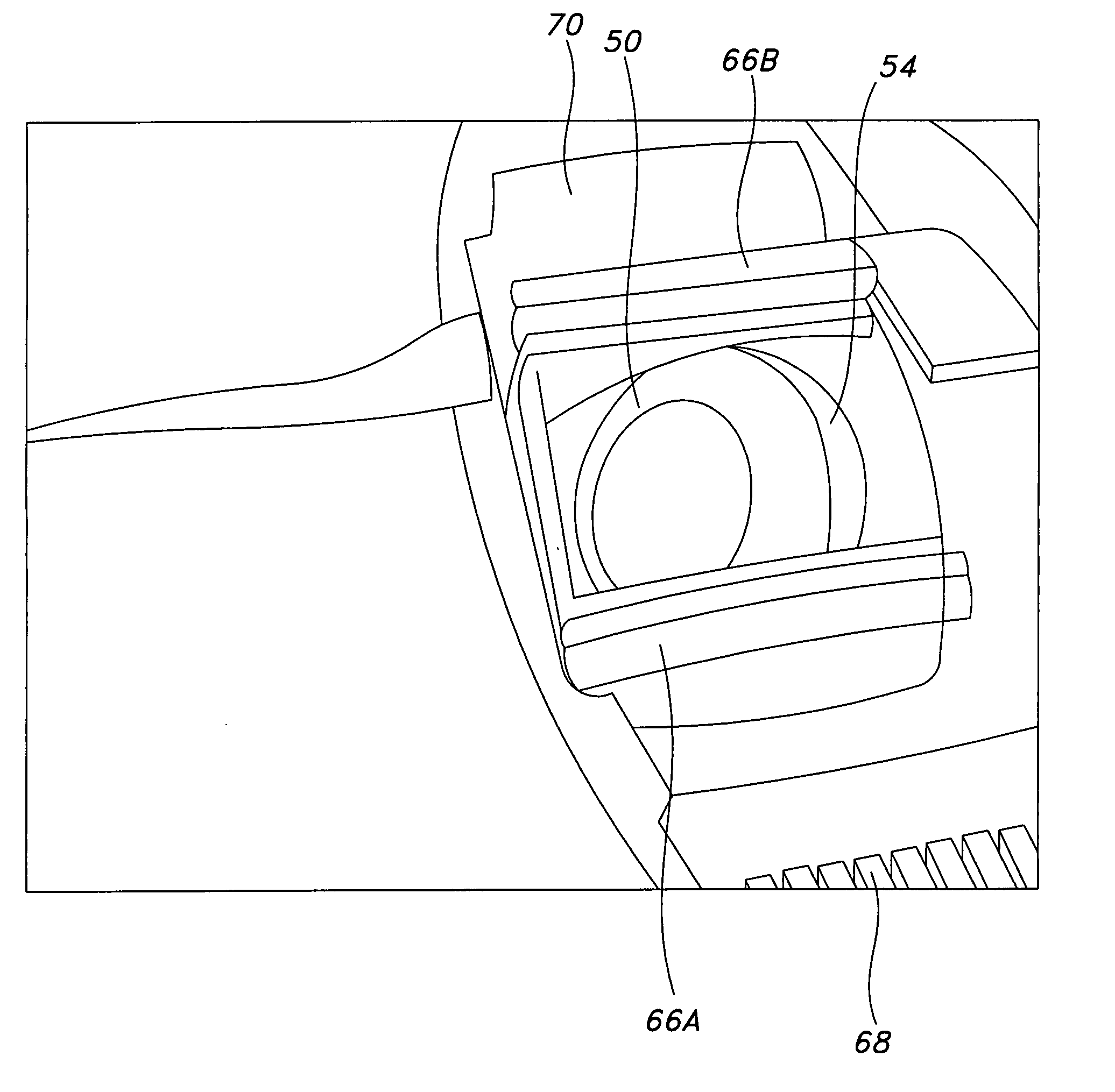
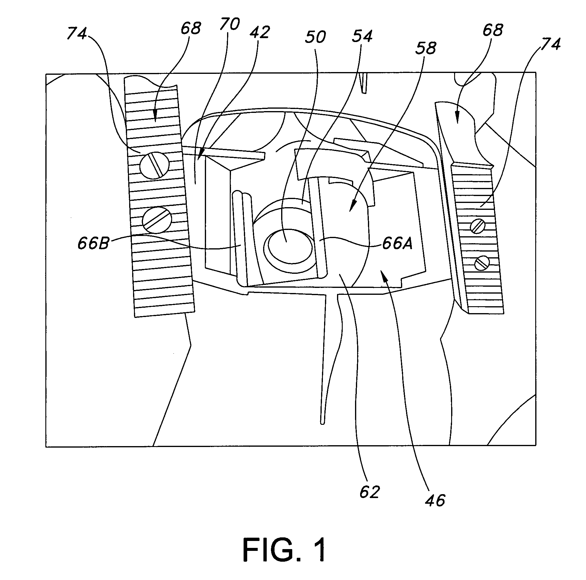
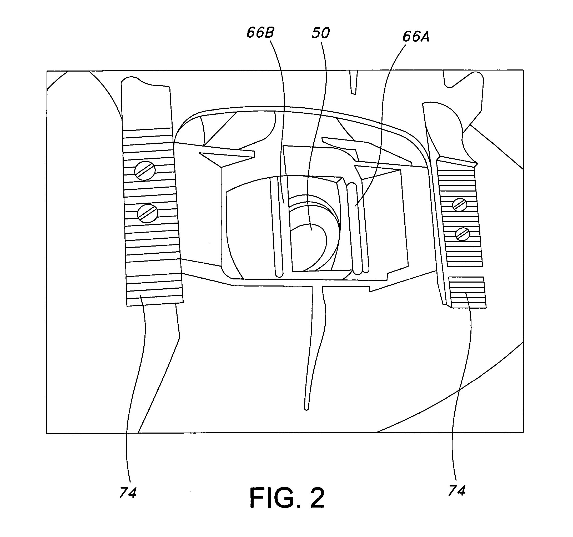
Automatic swimming pool cleaners and bodies, feet, discs, and other components thereof

a technology for swimming pools and cleaners, applied in cleaning equipment, domestic applications, applications, etc., can solve problems such as inhibiting undesired backward movement of cleaners, and achieve the effects of reducing the risk of cleaners sticking in the corners of pools, uniform flexibility, and improving the ability of cleaners

Active Publication Date: 2007-11-15
ZODIAC POOL CARE EURO
View PDF17 Cites 14 Cited by
  • Summary
  • Abstract
  • Description
  • Claims
  • Application Information

AI Technical Summary

Benefits of technology

[0011] Additionally, the present invention may incorporate novel apron and foot structure. Unlike conventional aprons and associated footpads, which have circular cross-section, aprons of the invention may be truncated in the normally-forward direction of travel and extend principally transversely beneath the cleaner body. These aprons thus may be wider than they are long, allowing their associated cleaner bodies to approach pool corners more closely before the cleaner discs lose suction with the pool floors. Bearing surfaces of the feet, moreover, may constitute elongated strips of material placed parallel to the normally-forward direction of travel of the cleaners, reducing the likelihood of their engaging obstructions in the pools.
[0012] Discs of the present inventi

Problems solved by technology

Such tabs or material, in particular, may inhibit undesired

Method used


Image

  • Automatic swimming pool cleaners and bodies, feet, discs, and other components thereof
  • Automatic swimming pool cleaners and bodies, feet, discs, and other components thereof
  • Automatic swimming pool cleaners and bodies, feet, discs, and other components thereof

Examples


Embodiment Construction

[0031] Well depicted in FIGS. 5 and 8 is an exemplary automatic swimming pool cleaner 10 of the present invention. Cleaner 10 is designed primary for attachment to the inlet, or suction side, of a pump of a swimming pool filtration system. Some or all aspects of the present invention are not necessarily limited to use with suction-side automatic swimming pool cleaners, however, and conceivably could be employed as part of other devices as well.

[0032] Shown in FIGS. 5 and 8 as part of cleaner 10 are body 14, inner pipe 18, and outer pipe 22. Similar to those of the cleaner described in the Kallenbach patent, inner and outer pipes 18 and 22 of cleaner 10 may be concentric, with outer pipe 22 adapted to be connected to a flexible hose leading, ultimately, to the inlet of a pump. Extending from body 14 may be arm 26, whose end 30 may contain a weight (not shown) functioning, in part, to balance a float (also not shown) typically positioned within body 14. However any weight need not ne...


PUM


Abstract

Devices for cleaning vessels, especially swimming pools, are discussed. The devices may include repositionable in-line valves, with the valves typically moving laterally (from side to side) and changing the initial direction of the main fluid-flow path through the valves and corresponding cleaner bodies. Asymmetric feet may be utilized as part of the devices, whose bottom bearing surfaces may include elongated strips of material placed parallel to the normally-forward direction of travel of the devices. Discs of non-uniform flexibility also may be employed, and blocking tabs or gripping material may be used to inhibit undesired backward movement of a cleaner when its operation commences.

Description

CROSS REFERENCE TO RELATED APPLICATION [0001] This application claims the benefit of U.S. Provisional Application No. 60 / 776,984 filed on Feb. 27, 2006, the contents of which are incorporated herein by reference.FIELD OF THE INVENTION [0002] This invention relates to devices for cleaning fluid-containing vessels and more particularly, but not exclusively, to automatic cleaners for swimming pools and components of such cleaners including, but not limited to, bodies, feet, and discs. BACKGROUND OF THE INVENTION [0003] Commonly-owned U.S. Pat. No. 4,642,833 to Stoltz, et al. (the “Stoltz Patent”) discloses various valve assemblies useful for automatic swimming pool cleaners. These assemblies typically include flexible, tubular diaphragms surrounded by chambers, with the diaphragms interposed in the fluid-flow paths (i.e. “in-line”) through the cleaners. In response to variation in pressure internally and externally, the diaphragms contract and expand transversely along at least part of...

Claims


Application Information

Patent Timeline
IPC IPC(8): E04H4/00
CPCE04H4/1663
Inventor MOORE, MICHAEL EDWARDVAN DER MEIJDEN, HENDRIKUS JOHANNES
Owner ZODIAC POOL CARE EURO
Why Eureka
Try Eureka