Compact filter comprising a square seal

a filter element and square seal technology, applied in the direction of filtration separation, liquid degasification, separation processes, etc., can solve the problems of increasing the service time, affecting the service life of the filter element, and requiring a considerable amount of effort to replace the filter element, so as to improve the use of space

Active Publication Date: 2007-11-15
MANN HUMMEL GMBH
View PDF10 Cites 29 Cited by
  • Summary
  • Abstract
  • Description
  • Claims
  • Application Information

AI Technical Summary

Benefits of technology

[0006] Another object of the invention is to provide a structurally simple filter with a filter element that can be serviced economically.
[0007] A furthe

Problems solved by technology

This embodiment has the disadvantage that the housing cover must be removed in the inflow area to replace the filter element, which requires the entire filter housing to be first removed from its installation position because th

Method used


Image

  • Compact filter comprising a square seal
  • Compact filter comprising a square seal
  • Compact filter comprising a square seal

Examples


Embodiment Construction

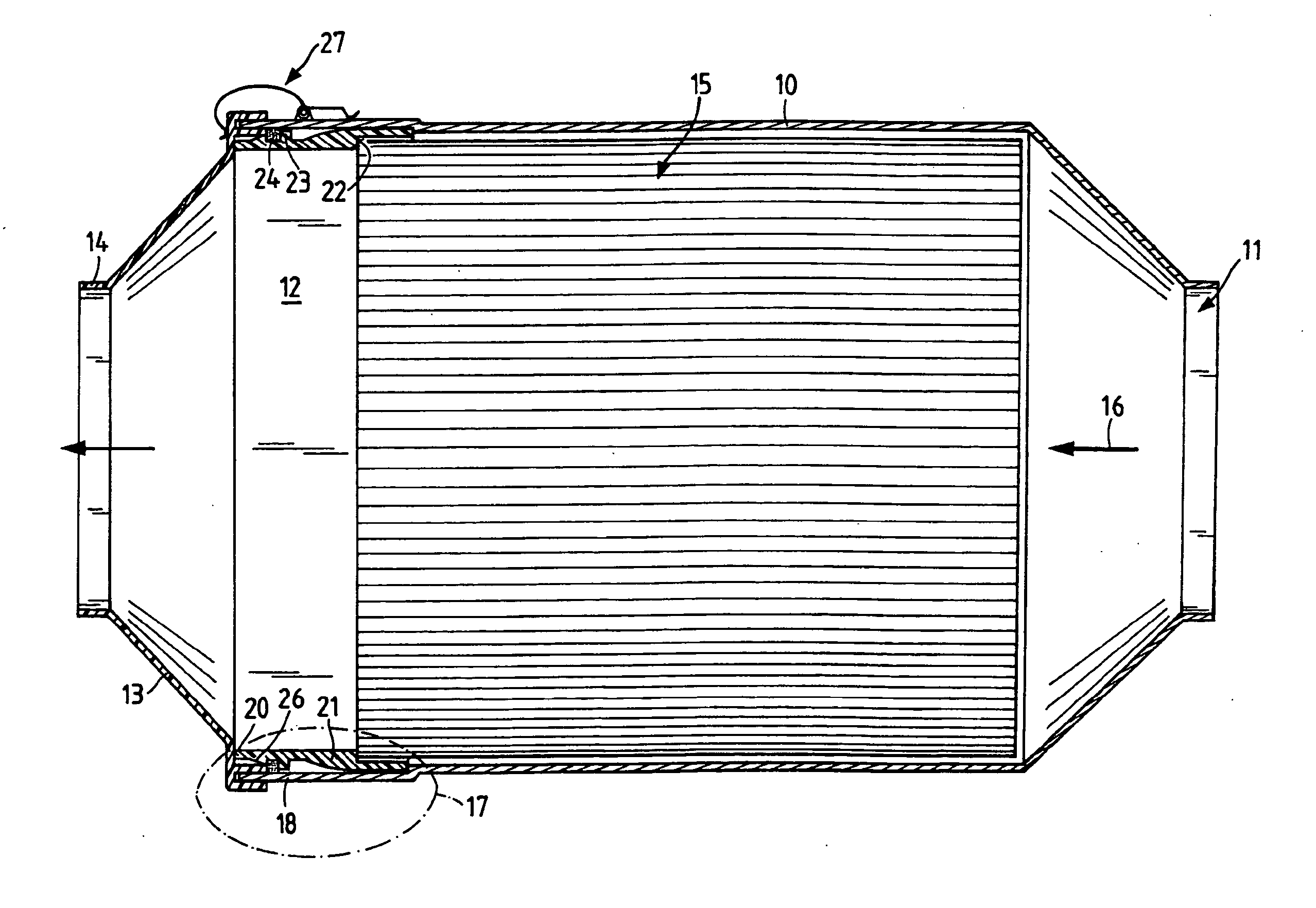
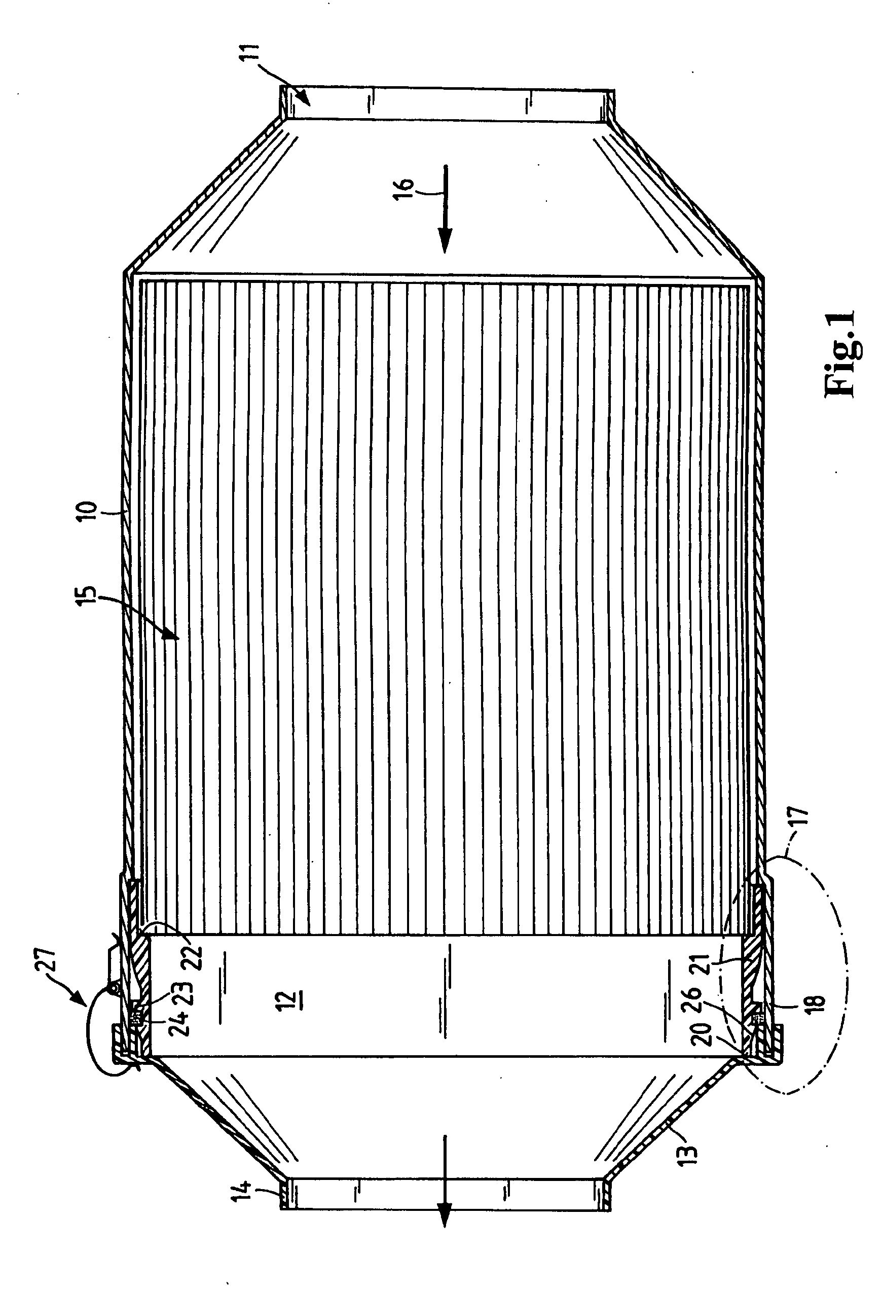
[0021] The filter system according to FIG. 1 comprises a housing 10 with a substantially concentric, oval or elliptical design. This housing 10 has an unfiltered air inlet 11 coupled to an unfiltered air intake fitting, which is not depicted here. A housing cover 13 is provided on the filtered air side 12. This cover also has a connection fitting 14, to which a filtered air line can be connected. A filter element 15 is located within the housing 10. This element corresponds to that described in WO 2004-020075, for example. The air flows through the filter element in the direction of arrow 16, and the filtered air leaves the filter element axially on the filtered air side 12.

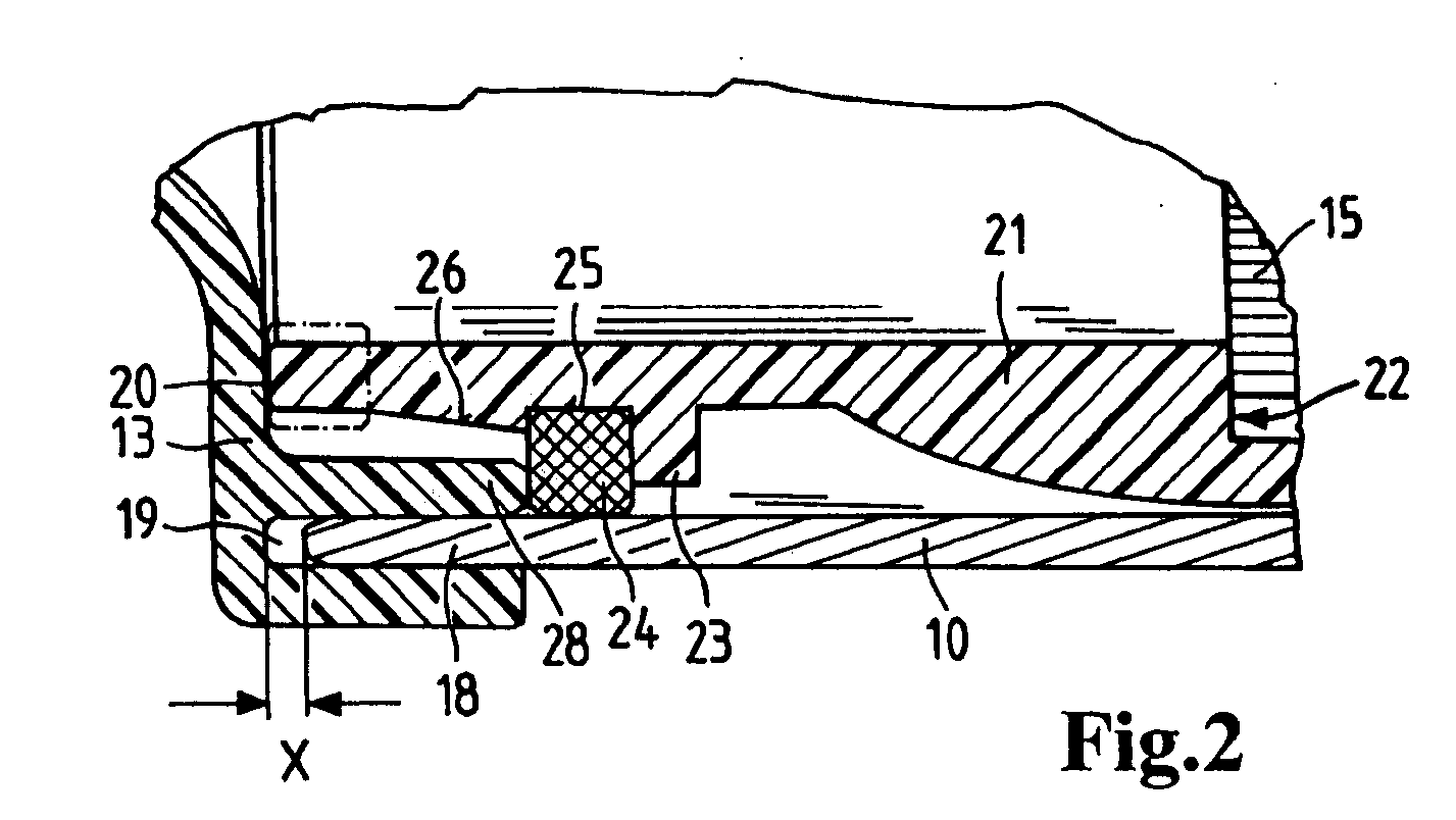
[0022] The connecting area 17, which extends over the entire circumference of the filter system, comprises both the fastening of the filter element 15 and the connection between the housing 10 and the housing cover 13.

[0023] This connection area is illustrated in greater detail in FIG. 2. Like components are id...


PUM

PropertyMeasurementUnit
Areaaaaaaaaaaa

Abstract

A filter element comprising a spirally wound filter through which a fluid to be filtered flows axially and which is provided with a mounting ring on the circumference of the wound filter secured to the wound filter by a welded, adhesive, extruded or fused joint. The mounting ring is provided with a circumferential profiled seal which engages a housing in which the filter element is installed to provide a seal between an unfiltered fluid side of the filter element and a filtered fluid side of the filter element.

Description

CROSS REFERENCE TO RELATED APPLICATIONS [0001] This application is a continuation of international patent application no. PCT / EP2005 / 054171, filed Aug. 24, 2005 designating the United States of America and published in German on Apr. 20, 2006 as WO 2006 / 040214, the entire disclosure of which is incorporated herein by reference. Priority is claimed based on Federal Republic of Germany patent application no. 10 2004 049,403.7, filed Oct. 8, 2004.BACKGROUND OF THE INVENTION [0002] This invention relates to a filter element comprising a spirally wound filter through which a fluid to be filtered flows axially. [0003] U.S. Pat. No. 6,322,602 B2 describes an air filter in a cylindrical air filter housing with a filter element designed for axial flow. At one axial end face in the area of the inflow side of the filter, the holding space for receiving the filter in the filter housing can be closed by a housing cover. To replace the filter element, the cover is detached, and the filter element...

Claims


Application Information

Patent Timeline
IPC IPC(8): B01D46/52
CPCB01D46/10B01D46/527B01D2279/60B01D2265/04B01D2271/027B01D2265/028
Inventor LAMPERT, JOHANNESPELZ, ANDREAS
Owner MANN HUMMEL GMBH
Why Eureka
Try Eureka