
Separation Systems with Charge Mosaic Membrane

a technology of mosaic membrane and separation system, which is applied in the direction of separation process, water/sewage treatment by ion exchange, centrifuge, etc., can solve the problems of difficult operation of many such systems, difficult to resolve the resolution of analytes, and high cost of hplc systems

Inactive Publication Date: 2007-11-15
GAJEK RYSZARD
View PDF10 Cites 17 Cited by
  • Summary
  • Abstract
  • Description
  • Claims
  • Application Information

AI Technical Summary

Benefits of technology

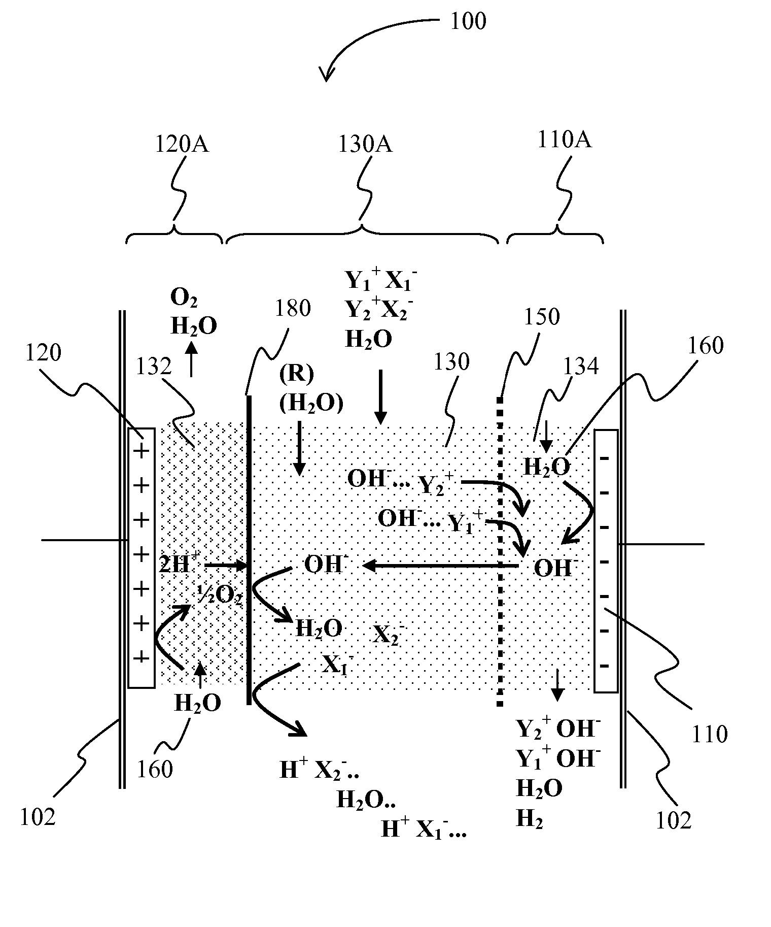
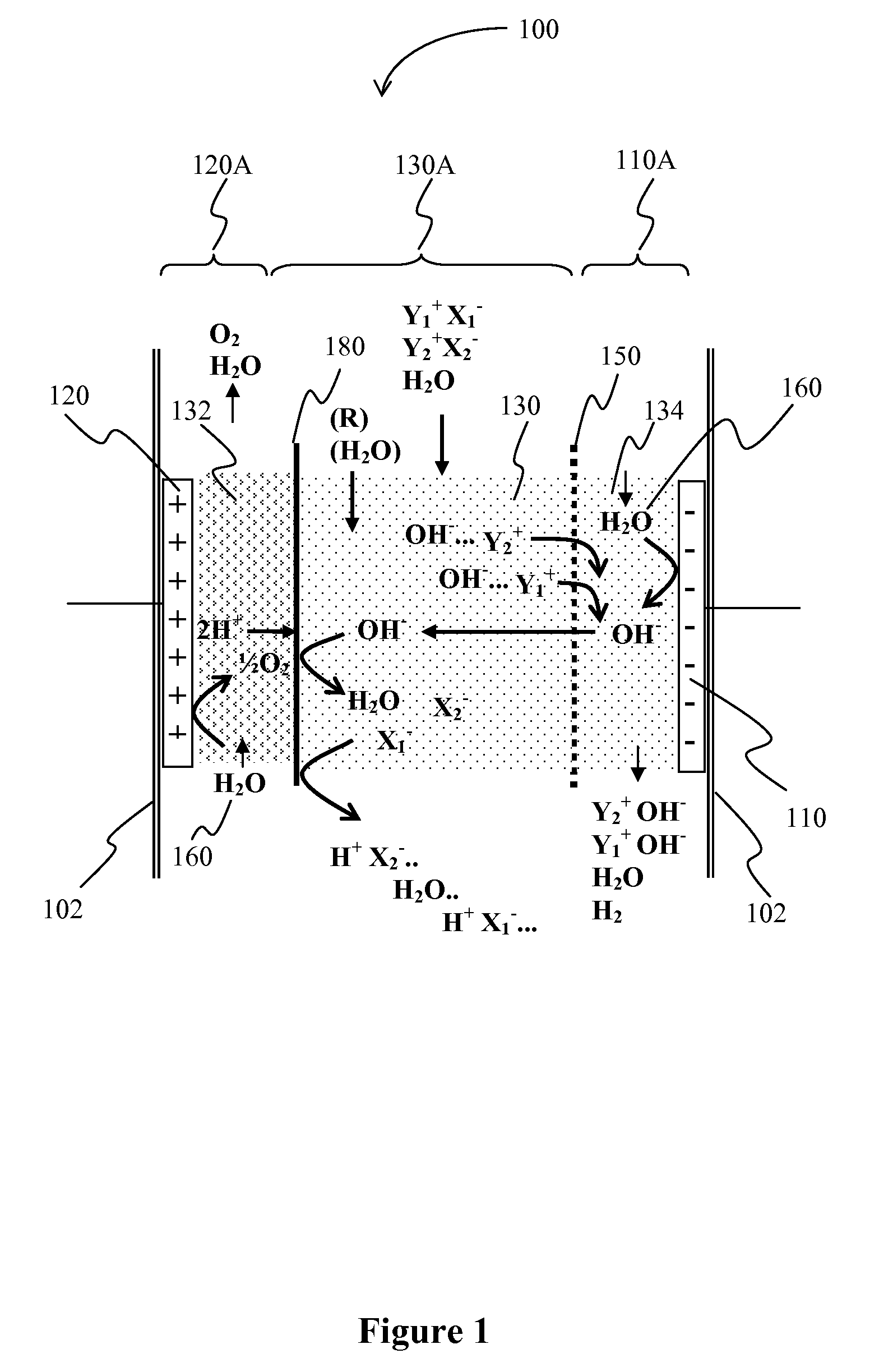
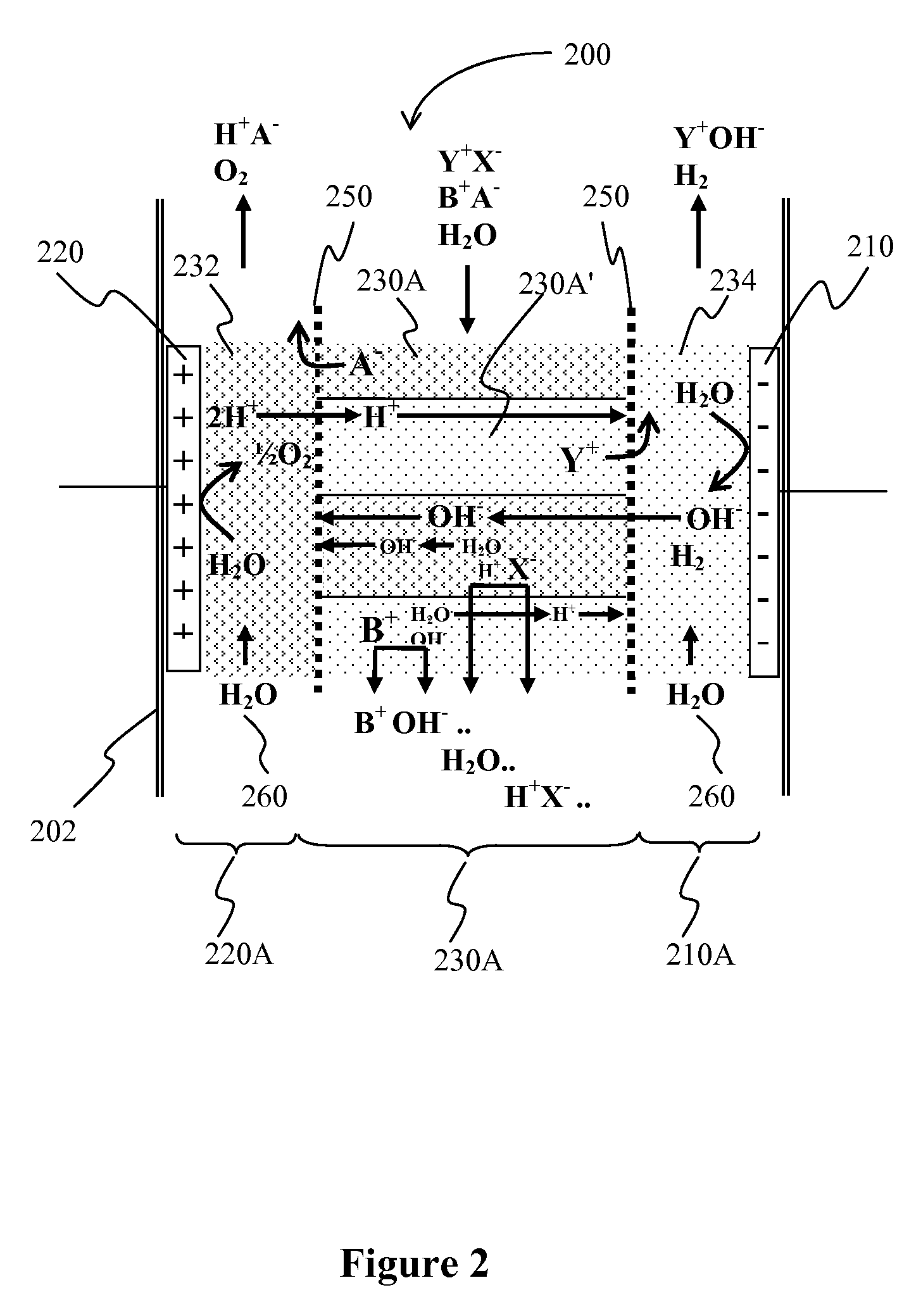
[0012] Thus, viewed from another perspective, contemplated systems may comprise an ion exchange resin that binds an ion from a fluid, wherein the ion is eluted from the resin using (a) an electric field generated between a cathode and an anode and (b) a second ion that is generated by electrolysis of the fluid by the cathode and the anode. In such systems, it is preferred that a charge mosaic membrane separates the ion exchange resin from the cathode, thereby allowing migration of OH− ions from the cathode to the ion exchange resin and migration of cations from the ion exchange resin to the cathode.

Problems solved by technology

While separations based on molecular weight differences are typically relatively independent on buffer conditions and other extraneous factors, resolution between analytes will often become increasingly problematic as the molecular weight difference decreases.
However, many of such systems are difficult to operate when the volume of the sample is relatively large (e.g., several liters).
Furthermore, HPLC systems are relatively expensive and frequently require extensive maintenance.
However, various difficulties remain.
Among other things, elution of a bound analyte will place the analyte in an environment that may not be compatible with further use or that may even interfere with the analyte's integrity of function.
However, many affinity reagents are relatively expensive (e.g., monoclonal antibodies) or may not be available for a desired analyte.
While many of the separation systems improve at least some aspects of resolution of a desired analyte, various problems still remain.
For example, analyte recovery is frequently problematic.
Furthermore, large scale preparation of analytes is often impracticable.
Thus, despite various known configurations and methods for separation of an analyte from a medium, all or almost all suffer from various problems.

Method used


Image

  • Separation Systems with Charge Mosaic Membrane
  • Separation Systems with Charge Mosaic Membrane
  • Separation Systems with Charge Mosaic Membrane

Examples


examples

[0073] The following examples are provided to further illustrate the inventive subject matter, and especially to provide further guidance to a practitioner with respect to CMM gradient separation and CMM buffered electrodialysis. (Membrane Dynamically Scanned Electrophoresis and Dynamically Buffered Electrodialysis).

CMM Buffered Electrodialysis—Dynamically Buffered Electrodialysis

[0074] Device Description:

[0075] Basic elements of a CMM buffered electrodialysis device are shown in FIG. 3. All ion-exchange materials are made similar to CMM Gradient Separation device. 1—Anode, 2—Anion-exchange screen, 3—Charge mosaic membrane, 4—Cathode, 5—Cation-exchange screen, 6—Bi-charge screen. The screen is prepared by thermally stitching 4 mm wide strips of cation- and anion-exchange screens together. Dimensions 5 cm wide and 20 cm high. 7A and 7B—Anode compartment water flow ports, 8A and 8B—Cathode compartment water flow ports, 9—Sample port, 10—Analyte port.

[0076] Continuous Operation Mod...


PUM

PropertyMeasurementUnit
MWaaaaaaaaaa
volumeaaaaaaaaaa
angleaaaaaaaaaa

Abstract

An ion is eluted from an ion exchange resin in a separation system using an eluent generated by electrolysis of a medium. Elution is further assisted by an electrical field between two electrodes, wherein the ion exchange resin is at least partially disposed between the electrodes. Particularly preferred aspects of such separation systems include gradient separation (Membrane Dynamically Scanned Electrophoresis—MDSE) and buffered electrodialysis (Dynamically Buffered Electrodialysis—DBE).

Description

[0001] This application is a continuation-in-part of our copending application with the Ser. No. 10 / 506,517, filed Sep. 2, 2004 which is a national phase of International patent application with the serial number PCT / US02 / 10444, filed Apr. 2, 2002, both of which are incorporated in their entirety by reference herein.FIELD OF THE INVENTION [0002] The field of the invention is electrophoresis-assisted separation of ionic species. BACKGROUND OF THE INVENTION [0003] Numerous disciplines in science and technology require separation and / or analysis of complex mixtures, or quantification, concentration, and / or removal of various analytes from such mixtures and there are various separation technologies known in the art. [0004] For example, individual analytes can be separated or isolated from mixtures using molecular weight differences between the analyte and the remaining compounds in the mixture. Size discrimination may be performed by size exclusion (e.g., using microporous matrix) or by...

Claims


Application Information

Patent Timeline
Patent Type & Authority Applications(United States)
IPC IPC(8): C02F1/42
CPCB01D15/361B01D15/362B01D15/363B01J49/0052B01D15/424B01J47/08B01D15/3885B01J49/30
Inventor GAJEK, RYSZARD
Owner GAJEK RYSZARD
Learn More