Display over gage instrument cluster

a display assembly and instrument technology, applied in the direction of thermometer details, landing aids, lighting support devices, etc., can solve the problems of limiting the space available for a large digital display, such as an lcd, occupying a significant amount of space, and occupying a large amount of area, so as to reduce the dynamic displacement of the display assembly and reduce the amount of space

Inactive Publication Date: 2007-11-15
VISTEON GLOBAL TECH INC
View PDF23 Cites 21 Cited by
  • Summary
  • Abstract
  • Description
  • Claims
  • Application Information

AI Technical Summary

Benefits of technology

[0015] In satisfying the above need, as well as overcoming the enumerated drawbacks and other limitations of the related art, the present invention provides a motor vehicle instrument cluster including an analog indicator assembly having a pointer rotatably coupled to an actuator for movement by the actuator and a display assembly including a display screen for displaying information to an occupant of the motor vehicle. A printed circuit board is electrically connected to the indicator assembly, the display assembly, and an electrical ground. A metal support frame is mounted to the printed circuit board and coupled thereby to the electrical ground.

Problems solved by technology

One drawback of large digital displays is that they occupy a significant amount of area.
Some of these indicators, such as speed, may be quite large.
This limits the amount of space available for a large digital display, such as an LCD.
A drawback to this configuration is that existing displays are cantilevered in front of the analog indicator using a simple, plastic frame.
For example, plastic is a high dielectric material, has low stiffness, and has poor thermal conductivity.
I

Method used


Image

  • Display over gage instrument cluster
  • Display over gage instrument cluster
  • Display over gage instrument cluster

Examples


Embodiment Construction

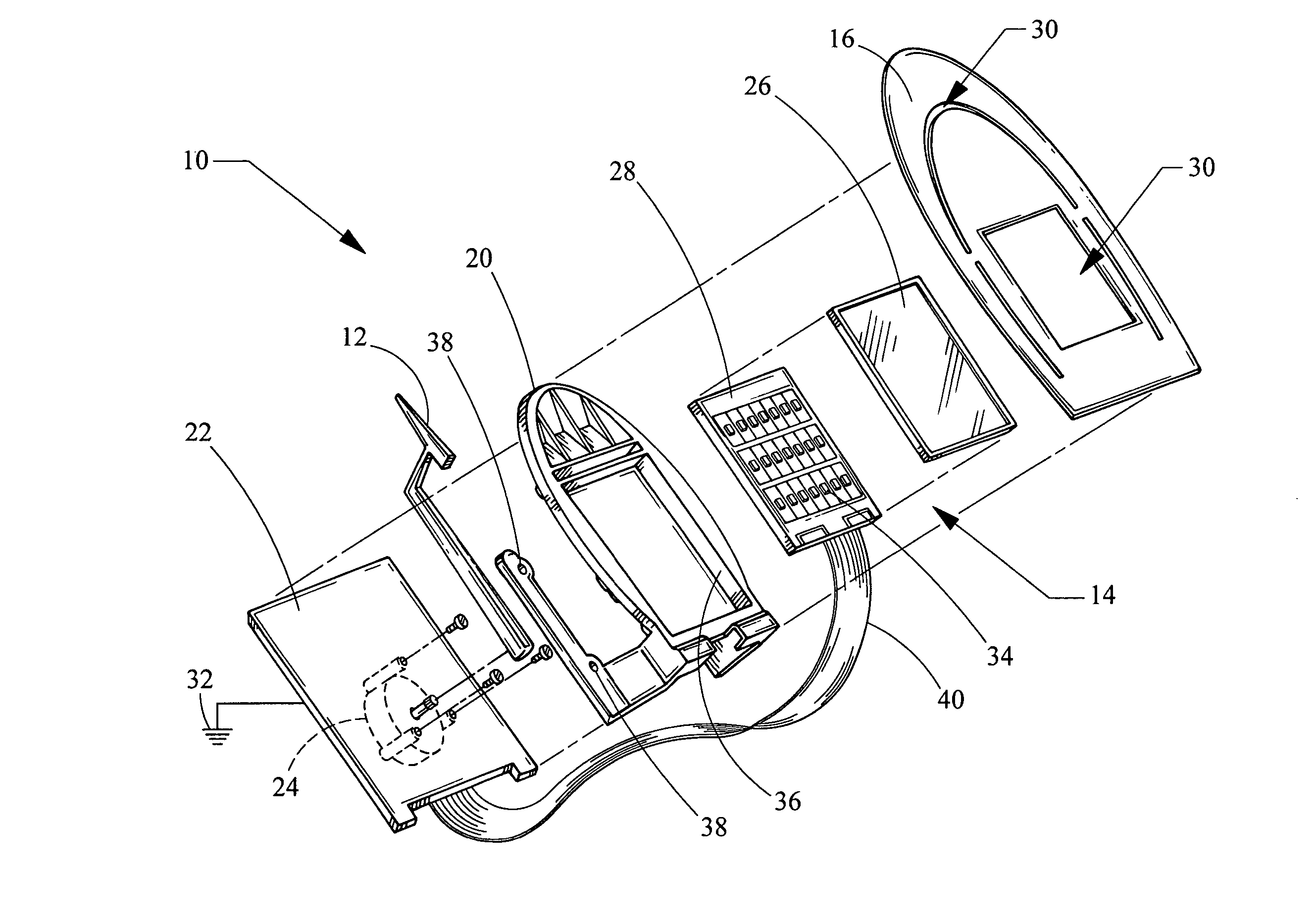
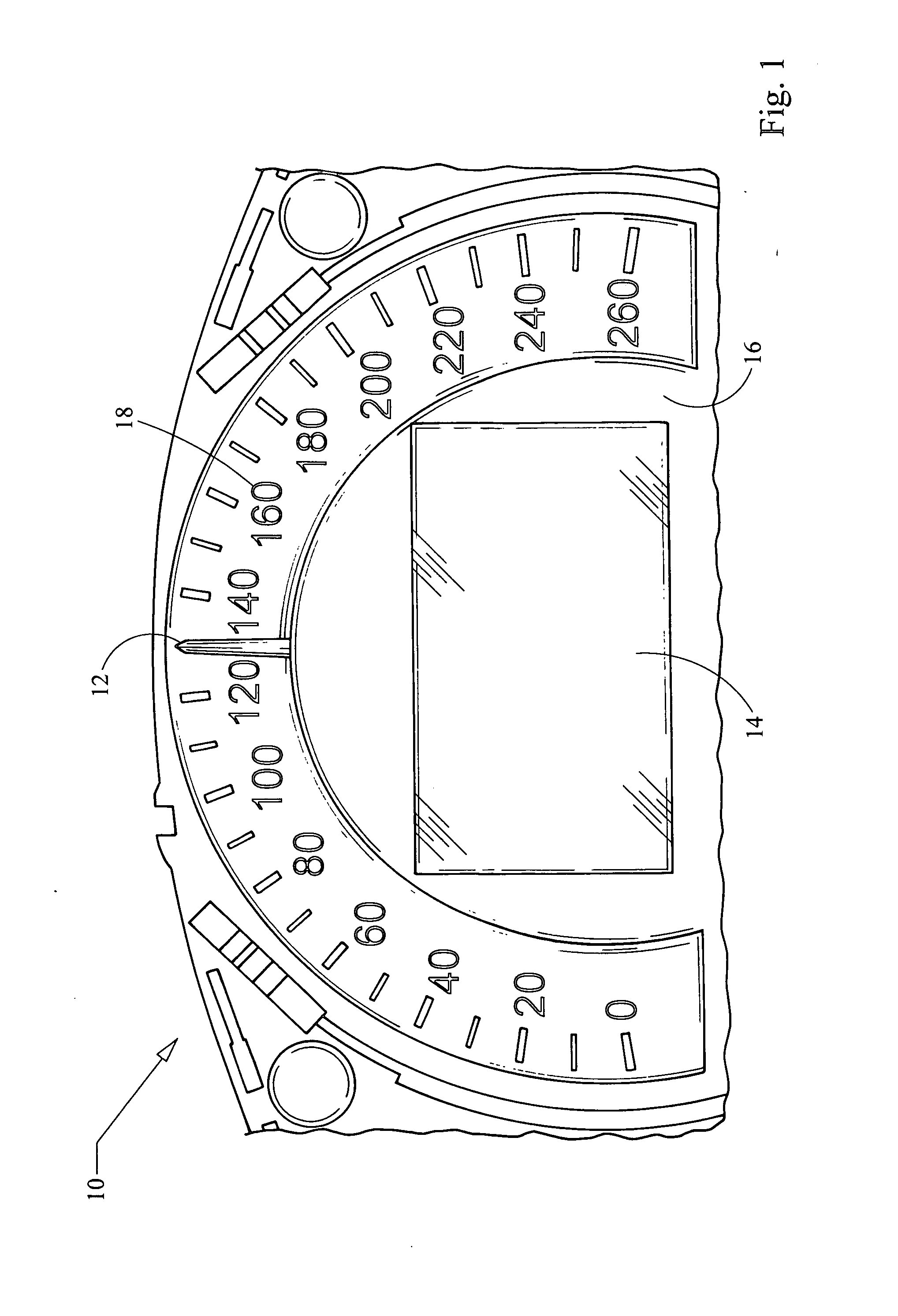
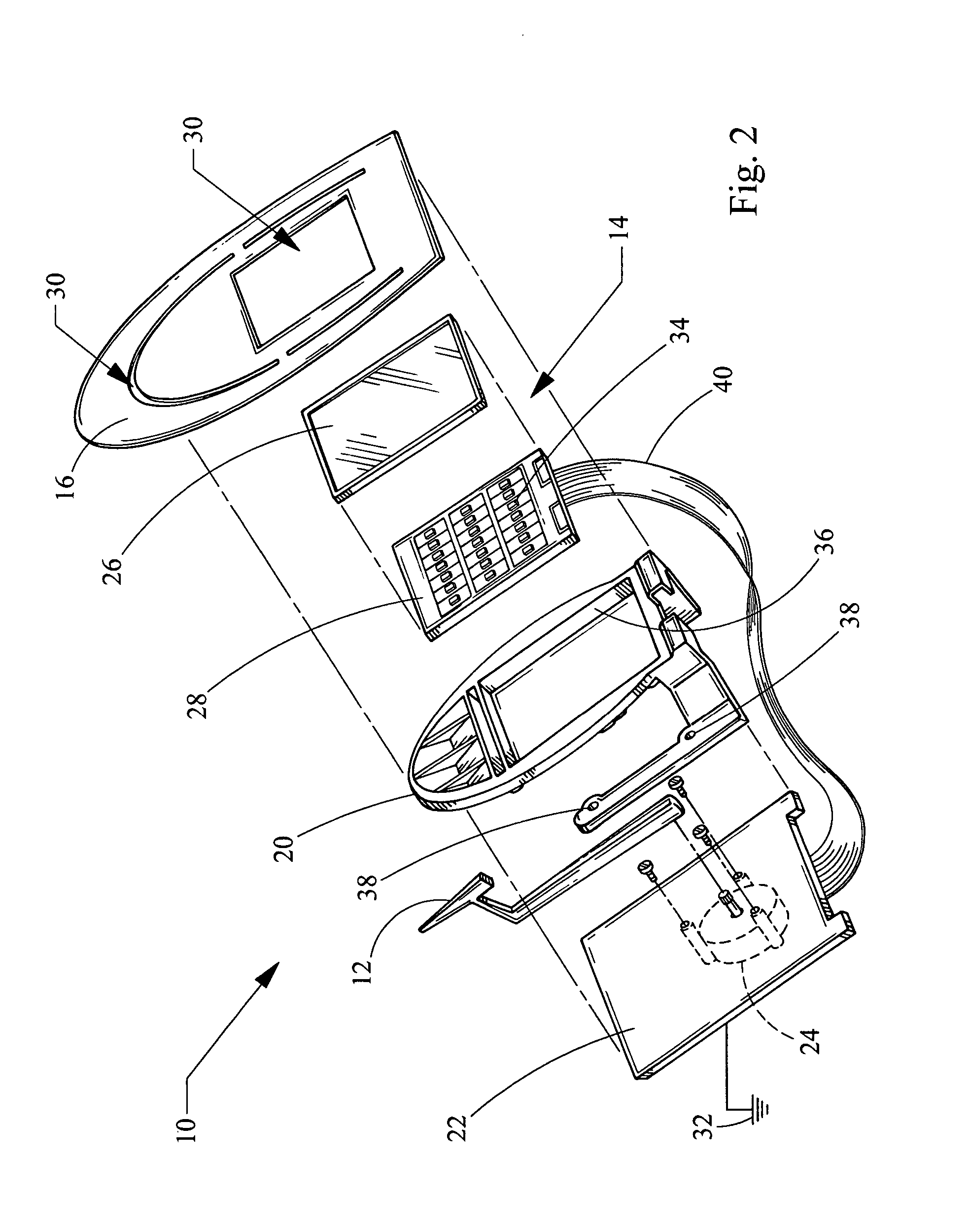
[0019] Referring now to the drawings, an instrument cluster embodying the principles of the present invention is illustrated in FIG. 1 and designated at 10. As its primary components, the instrument cluster 10 includes an analog pointer 12, a display assembly 14, and a face plate 16 having indicia 18 indicating, for example, vehicle speed. Additional features, shown in FIG. 2, include a frame 20 mechanically mounted and electrically coupled to a circuit board 22 and a motor 24, also mounted to the circuit board 22 and rotatably coupled to the pointer 12.

[0020] Looking more closely at the display assembly 14, it incorporates a flat panel display 26. The flat panel display 26 may be of any type capable of fitting within the instrument cluster 10, with typical examples including, but not limited to, liquid crystal displays (LCD), organic light-emitting diode (OLED) displays, and electrochromic displays. In some embodiments, such as that shown in FIG. 2, the flat panel display 26 may a...


PUM


Abstract

A motor vehicle instrument cluster comprising an analog indicator assembly having a pointer rotatably coupled to an actuator for a movement by the actuator, and a display assembly including a display screen for displaying information to an occupant of the motor vehicle and a printed circuit board electrically connected to the indicator assembly and the display assembly. In addition, the printed circuit board is electrically connected to an electrical ground and a metal support frame is mounted to the printed circuit board and coupled thereby to the electrical ground. The metal frame includes a support tray spaced apart from the printed circuit board, defining a gap in between. Finally, the display assembly is mounted in thermal communication to the support tray and the frame and the printed circuit board cooperate to define a static discharge path between the display assembly and the electrical ground.

Description

BACKGROUND [0001] 1. Field of the Invention [0002] The present invention generally relates to automotive instrument clusters. More specifically, the invention relates to instrument clusters where a display is located in front of an analog gage while allowing the analog pointer to remain visible. [0003] 2. Description of Related Art [0004] Originally, automobile instruments were analog devices. Using mechanical or electro-mechanical means, they displayed the operational status and performance of a motor vehicle. However, only factors that could be directly measured could be displayed to the driver. Common gages of this type are speedometers, tachometers, odometers, fuel level, oil pressure and the like. Each of these analog gages are connected to a sensor providing a signal in direct proportion to the value being measured. [0005] As technology has advanced, analog gages and sensors have been replaced by digital sensors and gages. A digital instrument panel, rather than being connecte...

Claims


Application Information

Patent Timeline
IPC IPC(8): G01D11/28
CPCB60K37/02B60K2350/203Y10S362/80G01D11/28B60K2350/1064G01D7/002B60K2370/154B60K2370/33B60K2370/698B60K2370/6985G01D2207/30
Inventor LUETTGEN, MICHAEL J.WEINDORF, PAUL F.L.SCHWEITZER, BRIAN C.
Owner VISTEON GLOBAL TECH INC
Why Eureka
Try Eureka