Adaptive jitter management control in decoder

a jitter management and decoder technology, applied in the field of adaptive jitter management control in decoders, can solve the problems of introducing a further delay to the received frames, called jitter delay, and achieve the effects of reducing end-to-end delay, reducing jitter buffer delay, and efficient jitter compensation

Inactive Publication Date: 2007-11-15
NOKIA CORP
View PDF7 Cites 42 Cited by
  • Summary
  • Abstract
  • Description
  • Claims
  • Application Information

AI Technical Summary

Benefits of technology

[0018] It is an advantage of the present invention that jitter compensation may be controlled efficiently by adjusting jitter delay in order to reduce end-to-end delay for transmission at the end of a period of active audio, since the end of an active audio burst can be determined reliable and immediately on the basis of the received information of audio activity and the jitter buffer delay can be decreased at the end of an active audio burst accordingly. Thus, assuming a two-way conversation, this may decrease the perceived delay.
[0019] According to an embodiment of the present invention, the discrete information of speech activity indicates the start and the end of at least one active audio burst of the audio signal.
[0020] According to an embodiment of the present invention, the discrete information of audio activity is generated by an audio activity detector, and wherein said audio activity detector is located in a transmitter.
[0021] According to an embodiment of the present invention, discrete information of audio activity is transmitted in each frame.
[0022] According to an embodiment of the present invention, said received frames are buffered in a variable buffer for compensating for jitter, said variable buffer having a variable buffer delay.
[0023] The variable buffer may have a variable buffer size and / or a variable buffer depth.

Problems solved by technology

Such a jitter compensation, which may be performed by a jitter buffer, introduces a further delay to the received frames, the so called jitter delay.

Method used


Image

  • Adaptive jitter management control in decoder
  • Adaptive jitter management control in decoder
  • Adaptive jitter management control in decoder

Examples


Embodiment Construction

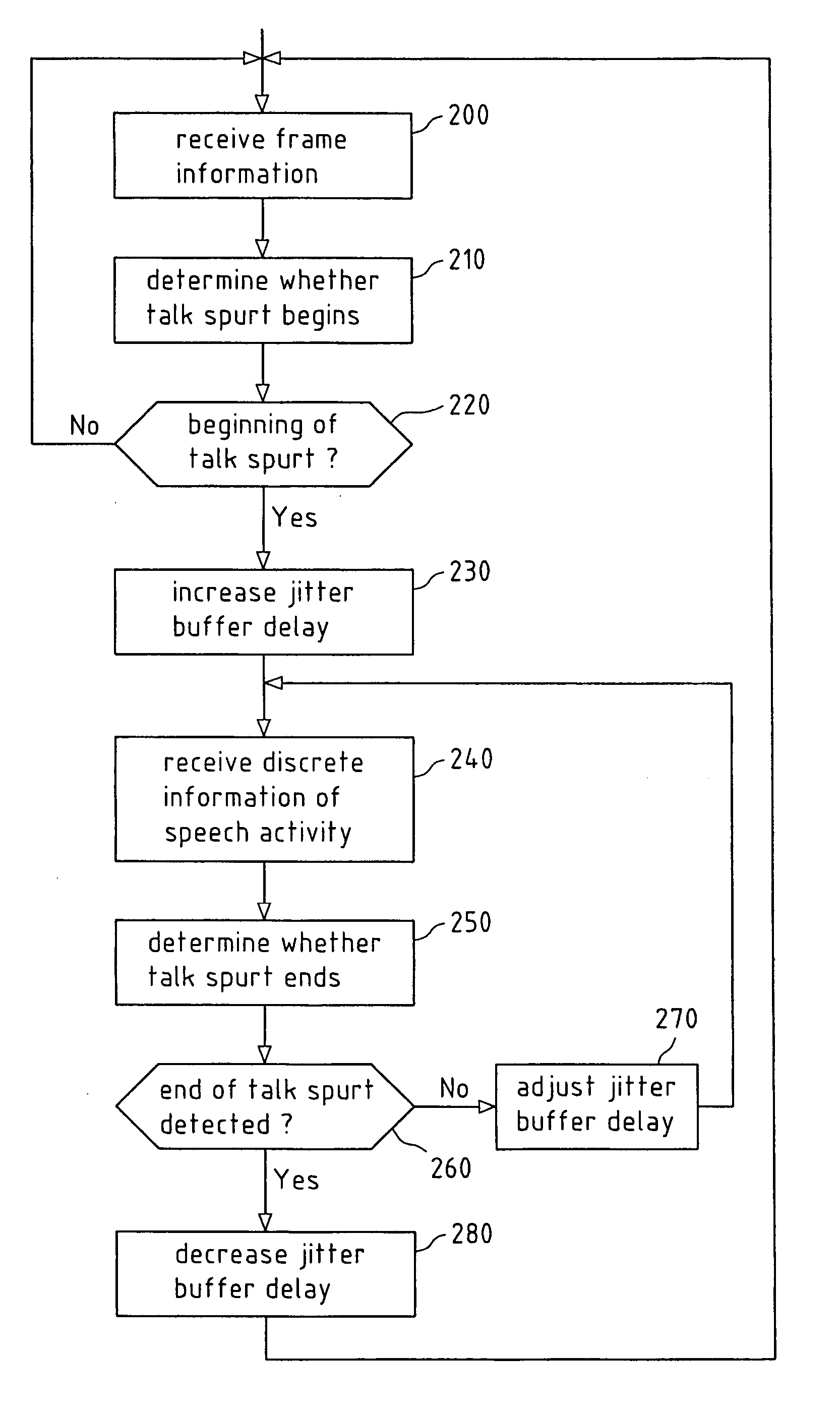
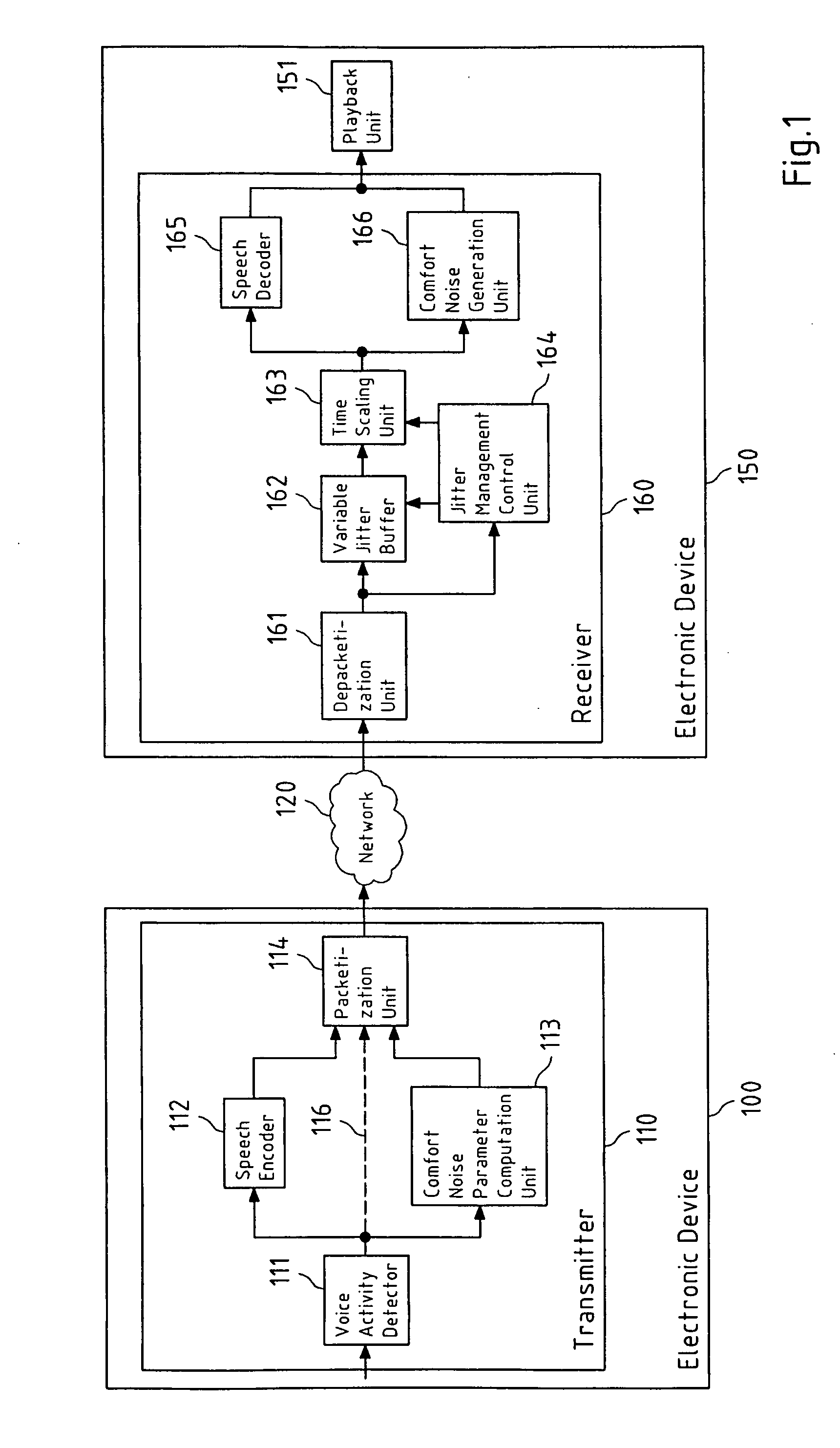
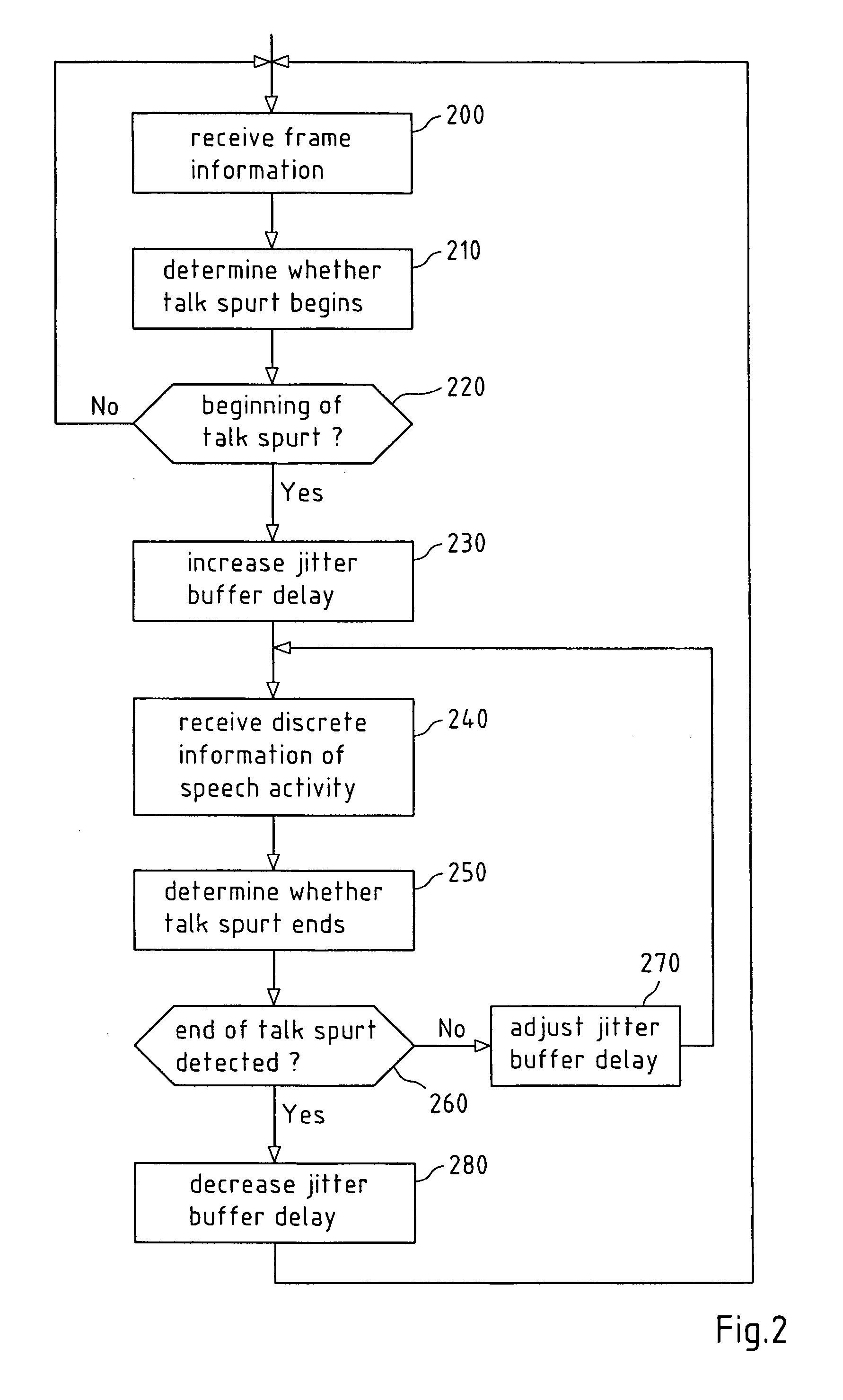
[0064]FIG. 1 is a schematic block diagram of an exemplary transmission system, in which enhanced adaptive jitter management control according to an exemplary embodiment of the invention may be implemented.

[0065] The system comprises an electronic device 100 with a transmitter 110, a packet switched communication network 120 and an electronic device 150 with a receiver 160. The transmitter 110 may represent a Voice over IP (VoIP) transmitter and the receiver 160 may represent a corresponding VoIP receiver.

[0066] The voice activity detector (VAD) 111 receives audio / voice frames from the electronic device 100 and classifies every audio frame as active speech frame or non-active speech frame. Correspondingly the VAD 111 generates discrete information of audio activity, i.e. of speech activity, which indicates whether the actual frame is classified as active speech frame or as non-active speech frame. Thus, the discrete information of audio activity may indicate the start and the end o...


PUM


Abstract

A method, a chipset, a receiver, a transmitter, an electronic device and a system for enabling a control of jitter management of an audio signal is described, wherein the audio signal is distributed to a sequence of frames that are received via a packet switched network, the received frames comprising active audio frames and non-active audio frames, wherein a concatenation of subsequent active audio frames represents an active audio burst, wherein a discrete information of audio activity of the audio signal via the packet switched network is received, the end of an active audio burst is determined based on the received discrete information of audio activity, and wherein jitter compensation of the received frames is controlled on the basis of the determined end of an active audio burst. The invention further relates to a corresponding software program product storing a software code for controlling jitter management of an audio signal.

Description

FIELD OF THE INVENTION [0001] This invention relates to a method, to a chipset, to a receiver, to a transmitter, to an electronic device and to a system enabling a control of jitter management of an audio signal. The invention further relates to a software program product storing a software code for controlling jitter management of an audio signal. BACKGROUND OF THE INVENTION [0002] Jitter management is a major issue in Voice over IP (VoIP) design. Network jitter has two components: high frequency component and low frequency component. The conventional jitter buffer holds an initial playback of the incoming voice packet stream to accommodate the high frequency component of jitter. The slowly varying component of the jitter is often resolved by an adaptive jitter buffer, which dynamically changes the target jitter buffer depth according to the network condition. However, both methods introduce initial buffering delay, which may be even several tens of milliseconds in typical wireless...

Claims


Application Information

Patent Timeline
Patent Type & Authority Applications(United States)
IPC IPC(8): H04J3/06
CPCG10L19/005H04J3/0632G10L19/012
Inventor OJALA, PASILAKANIEMI, ARI
Owner NOKIA CORP
Why Eureka
Try Eureka