Method and apparatus for region-based moving image encoding and decoding

a technology of moving image and region, applied in the field of method and apparatus for region-based moving image encoding and decoding, can solve the problems of natural limit in encoding which can be adapted to the scene structure or features of images, limit each region to a rectangular shape, etc., and achieve the effect of facilitating more accurate region partitioning and accurate decoding

Inactive Publication Date: 2007-11-15
SEKIGUCHI SHUNICHI +2
View PDF42 Cites 12 Cited by
  • Summary
  • Abstract
  • Description
  • Claims
  • Application Information

AI Technical Summary

Benefits of technology

[0012] The present invention takes into consideration these problems with the object of providing a moving image encoding technique for performing more flexible processing according to the conditions of the image to be processed. The object of this invention, in more concrete terms, is to provide a moving image encoding technique using region partitioning techniques that can accurately handle various image structures. Another object of this invention is to provide a partitioning criterion based on various points of view when partitioning regions for encoding. Still another object of this invention is to provide a technique for correctly decoding the encoded data of regions that have been partitioned into various shapes.
[0013] The moving image encoding method of this invention includes two steps. A first step partitions an input image into multiple regions based on a predetermined partitioning judgment criterion. Until this point, the encoding process is the same as the general conventional region-based encoding. However, in a second step, this invention integrates each of partitioned multiple regions with adjacent regions based on a predetermined integration judgment criterion. Thereafter, in a third step, the image signal is encoded for each of the regions remaining after integration. According to this method, the integration process allows regions to take on various shapes. Thus, a region having a shape closely matching the structure of an image or outline of an object can be generated.
[0014] The moving image encoding apparatus of this invention includes a region partitioning section and an encoder. The region partitioning section includes a partitioning processing section for partitioning the input image into multiple regions based on a predetermined partitioning judgment criterion, and a integration processing section for integrating each of multiple regions partitioned by the partitioning processing section with adjacent regions based on a predetermined integration judgment criterion. The encoder encodes the image signal for each of the regions remaining after integration by the integration processing section. According to this apparatus, a comparatively high image quality can be achieved at comparatively high data compression ratios while flexibly supporting the structures of images.
[0016] The above-mentioned partitioning processing section includes a class identifying section for classifying the importance of regions into classes, and may judge whether or not to partition each region based on an activity to be described later and the class. If the class identifying section references feature parameters in images, the recognition of objects becomes possible thus facilitating more accurate region partitioning.
[0017] On the other hand, the moving image decoding apparatus of this invention inputs and decodes the encoded data of the image that was encoded after being partitioned into multiple regions. This apparatus includes a region shape restoring section and an image data decoder. The region shape restoring section restores, based on region shape information included in the encoded data, the shape of each region that was partitioned during encoding. The image data decoder, after specifying the sequence in which regions were encoded based on the shapes of the restored regions, decodes the image for each region from the encoded data. According to this apparatus, accurate decoding is achieved even if regions having various shapes are generated in the encoding stage.

Problems solved by technology

Therefore, there is naturally a limit in the encoding which can be adapted to the scene structure or features of an image.
However, this apparatus also limits each region to a rectangular shape.

Method used


Image

  • Method and apparatus for region-based moving image encoding and decoding
  • Method and apparatus for region-based moving image encoding and decoding
  • Method and apparatus for region-based moving image encoding and decoding

Examples


first embodiment

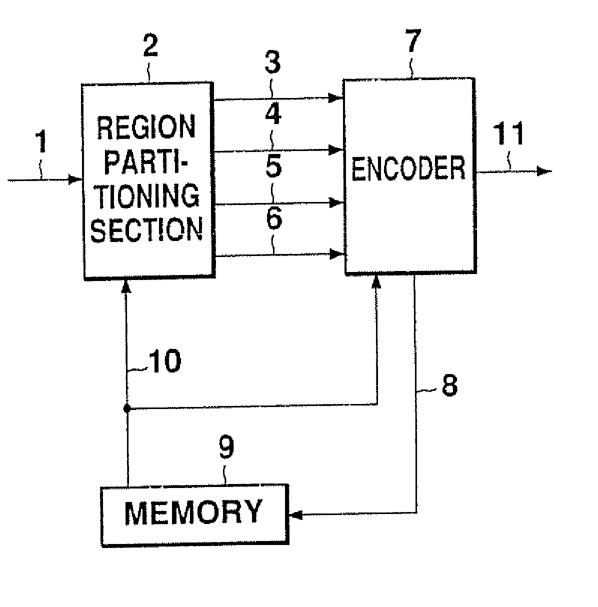
[0046]FIG. 3 is a block diagram showing a configuration of a moving image encoding apparatus related to this embodiment. This apparatus can be used in portable or stationary equipment for image communications, such as TV telephones and TV conferencing. It can also be used as a moving image encoding apparatus in image storage and recording apparatus such as digital VCRs and video servers. Furthermore, the processes in this apparatus can also be used as a moving image encoding program to be installed in the form of software or DSP firmware.

[0047] In FIG. 3, numeral 1 indicates the input image, numeral 2 indicates a region partitioning section, numeral 3 indicates region shape information, numeral 4 indicates a region image signal, numeral 5 indicates region motion information, numeral 6 indicates region attribute information, numeral 7 indicates an encoder, numeral 8 indicates a local decoded image, numeral 9 indicates a memory, numeral 10 indicates a reference image, and numeral 11 ...

second embodiment

[0080] This embodiment relates to an apparatus wherein region partitioning section 2 of the first embodiment has been partially modified. FIG. 16 is an internal block diagram of region partitioning section 2 in this embodiment. As shown in this diagram, region partitioning section 2 of the second embodiment has a configuration wherein partitioning processing section 12 of FIG. 5 has been replaced by uniform partitioning section 15. As shown in FIG. 17, a threshold judgment of the activity is not performed in the initial partitioning process in this configuration, and uniform partitioning is unconditionally performed in square blocks of minimum region area. This minimum region area may be made selectable.

[0081] Setting of the threshold is unnecessary in this embodiment, and region partitioning is performed only for amount of code—distortion cost as the evaluation value. Therefore, the procedure associated with threshold setting becomes unnecessary, as do activity calculation and com...

third embodiment

[0082] In the partitioning process of this embodiment, a judgment is made as to whether or not partitioning is possible, not only including the activity, but also including an index (hereinafter called a class) indicating the importance of the region. It is preferable to perform detailed encoding for regions having high importance, and to reduce region areas. Regions having low importance are made as large as possible so as to reduce the amount of code per pixel.

[0083] The activity is, for example, a closed, local statistical value within the region. On the other hand, the classes in this embodiment are based on the features of the image spanning regions. In this embodiment, the classes are defined on the basis as to what degree a person views the region, namely, a person's degree of observation, due to the object structure traversing the region. For example, when the edge distribution of a given region spans a wide range and the connection with adjacent regions is strong, it is hi...


PUM


Abstract

In partitioning and encoding an image into multiple regions, the degree of freedom of the region shape has generally been low and setting regions based on image features was difficult. A moving image encoding apparatus includes a region partitioning section, an encoder, and a memory for motion-compensated prediction. The region partitioning section includes a partitioning processing section and a integration processing section. The partitioning processing section partitions the input image based on a criterion relating to the state of partition. The integration processing section integrates mutually close regions based on a criterion relating to the state of integration. Thereafter, each region is encoded. A large variety of region shapes can be produced by the integration processing section.

Description

[0001] This application is a Divisional of co-pending application Ser. No. 11 / 531,633 filed Sep. 13, 2006, which is a Divisional of Ser. No. 10 / 347,386 filed Jan. 21, 2003, which is a Divisional of Ser. No. 08 / 956,106 filed Oct. 24, 1997, and for which priority is claimed under 35 U.S.C. § 120; and this application claims priority of Application Nos. 9-107072 and 9-261420 filed in Japan on Apr. 24, 1997 and Sep. 26, 1997, respectively, under 35 U.S.C. § 119; the entire contents of all are hereby incorporated by referenceBACKGROUND OF THE INVENTION [0002] 1. Field of the Invention [0003] This invention relates to a method and apparatus for inputting and encoding a moving image and to an apparatus for decoding the encoded moving image. This invention particularly relates to a technique for encoding an image frame by first partitioning it into multiple regions and to a technique for decoding the encoded image frame. [0004] 2. Description of the Related Art [0005]FIG. 1 is a block diagr...

Claims


Application Information

Patent Timeline
Patent Type & Authority Applications(United States)
IPC IPC(8): H04N7/12H04B1/66H04N19/119G06T1/00G06T9/00H04N7/24H04N19/00H04N19/124H04N19/134H04N19/136H04N19/137H04N19/139H04N19/14H04N19/147H04N19/172H04N19/176H04N19/189H04N19/196H04N19/20H04N19/423H04N19/46H04N19/50H04N19/503H04N19/51H04N19/567H04N19/61H04N19/625H04N19/70H04N19/86H04N19/94
CPCH04N19/176H04N19/119H04N19/147H04N19/30H04N19/15H04N19/19H04N19/124H04N19/14H04N19/137H04N19/146H04N19/17H04N19/61
Inventor SEKIGUCHI, SHUNICHIISU, YOSHIMIASAI, KOHTARO
Owner SEKIGUCHI SHUNICHI
Why Eureka
Try Eureka