
Drive transmission mechanism and image forming device

a transmission mechanism and image technology, applied in the direction of yielding coupling, electrographic process apparatus, instruments, etc., can solve the problems the number of assembling man-hours, and achieve the effect of increasing the number of components

Inactive Publication Date: 2007-11-15
MURATA MASCH LTD
View PDF5 Cites 104 Cited by
  • Summary
  • Abstract
  • Description
  • Claims
  • Application Information

AI Technical Summary

Benefits of technology

[0008]In order to overcome the problems described above, according to preferred embodiments of the present invention, axial center displacement in two axial directions can be smoothly absorbed, and then a drive can be transmitted from a driving member to a driven member.
[0010]According to another preferred embodiment of the present invention, even if displacement in two axial directions occurs between the driving member and the driven member, the displacement can be absorbed at the spaces in each of the coupling portions. Therefore, stress strain is not generated on the driving member and the driven member, and drive transmission can be smoothly carried out. Moreover, since the above-described function can be achieved by a coupling relationship between the driving member and the driven member via one coupling member, a number of components and a number of assembling man-hours do not increase. In addition, the coupling member can be preferably made of hard resin and metal etc., and consequently, the intensity and reliability of the components is secured.
[0012]According to various preferred embodiments of the present invention, the driving member and the driven member can be coupled smoothly via the coupling member. Along with this coupling, the axial center displacement in one axial direction is absorbed by the space portion. Moreover, a degree of freedom of relative movement between the action portion of the action protrusion and the acted-on portion of the coupling member increases. In addition, frictional resistance at a contact portion can be reduced, and noise occurrence during drive can also be reduced.
[0017]According to another preferred embodiment of the present invention, even if the axial center displacement in two axial directions occurs between the driving member on a device main body side and the rotation mechanism on a process unit side, the axial center displacement in two axial directions can be absorbed by the coupling member. Thus, the drive transmission can be smoothly carried out. Accordingly, the inserting and removing operation of the process unit is easily performed by inserting and removing the process unit from a side portion of the device main body. Moreover, it is more effective to include the above-described drive transmission mechanism in a developing unit because the developing unit includes a plurality of rotation mechanisms, and also includes a structural and functional feature in which the rotation mechanism is rotationally driven in a resin casing which contains developer.

Problems solved by technology

Moreover, since the above-described function can be achieved by a coupling relationship between the driving member and the driven member via one coupling member, a number of components and a number of assembling man-hours do not increase.

Method used


Image

  • Drive transmission mechanism and image forming device
  • Drive transmission mechanism and image forming device
  • Drive transmission mechanism and image forming device

Examples


Embodiment Construction

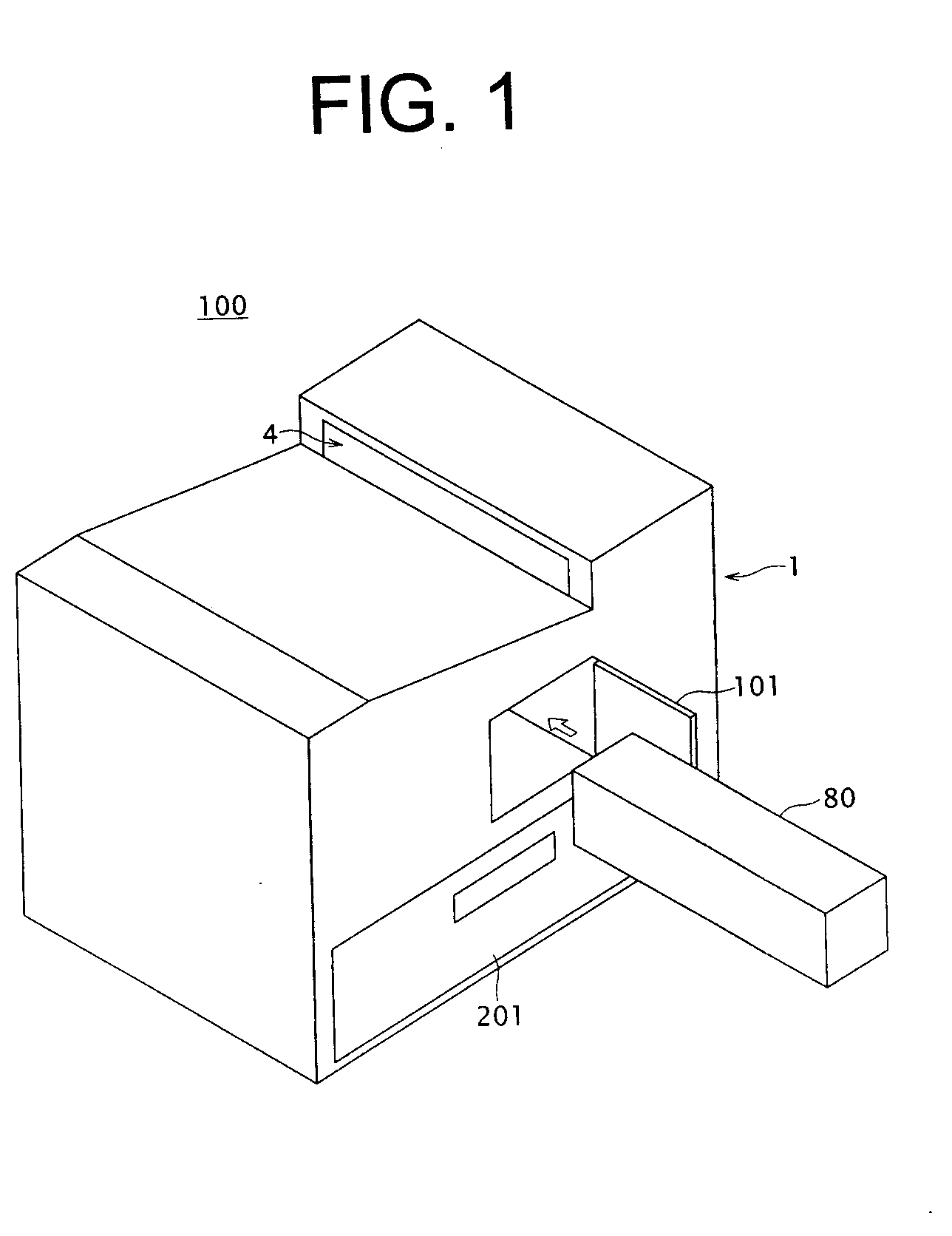
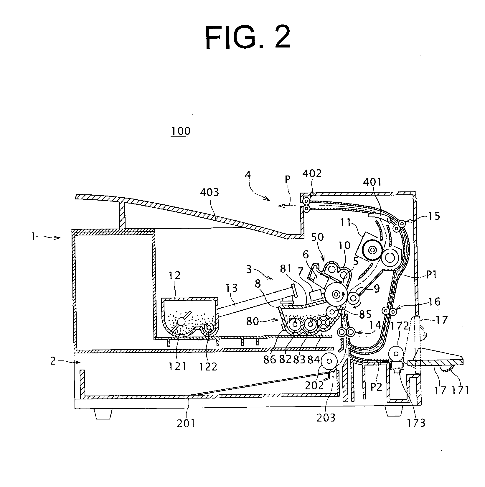
[0025]An image forming device 100 illustrated in FIGS. 1 and 2 is a printer including an electrophotographic printing unit as an example. The image forming device 100 is not limited to the illustrated example, and may be a copier, a facsimile machine, or a Multi Function Peripheral (MFP) including a copier function and / or a facsimile function including an image scanning device. In a device main body 1 of the image forming device 100, a paper feeding unit 2 for printing papers, an electrophotographic image printing unit 3, and a discharge unit 4 where printed out papers are discharged, are sequentially stacked in a height direction of the device main body 1. The paper feeding unit 2 includes a paper feed cassette 201, a paper separating and feeding roller 202, and a separating pad 203. The paper feed cassette 201 can accommodate a plurality of stacked printing papers, and can be removably inserted into the device main body 1. The paper separating and feeding roller 202 is arranged at...


PUM


Abstract

A direction in which a drive transmission acts on a driving member and a coupling member at a coupling portion is perpendicular or substantially perpendicular to a direction in which the drive transmission acts on the coupling member and a driven member at a coupling portion. In both of the coupling portions, spaces are provided so that the driving member and the coupling member, and the coupling member and the driven member, can be respectively coupled to each other under a state in which mutual displacement is permitted in a direction that is perpendicular or substantially perpendicular to each drive transmission action direction.

Description

BACKGROUND OF THE INVENTION[0001]1. Field of the Invention[0002]The present invention relates to a drive transmission mechanism. Furthermore, the present invention relates to an image forming device including an electrophotographic process unit which has an axial rotation mechanism and can be removably inserted into a device main body. In particular, the present invention relates to a drive transmission mechanism for transmitting a drive force to the axial rotation mechanism, and relates to the image forming device including such a drive transmission mechanism.[0003]2. Description of the Related Art[0004]An electrophotographic printing unit is frequently used in an image forming device. The image forming device is adopted in a copier, a facsimile machine, a printer, or a Multi Function Peripheral (MFP) including a copying function, a facsimile function, and / or a printing function or the like. In the electrophotographic printing unit, process portions are unitized into a process unit...

Claims


Application Information

Patent Timeline
IPC IPC(8): G03G15/00
CPCF16D3/04F16D3/10G03G15/0806G03G21/1676G03G2221/1657G03G21/1647G03G15/0896G03G15/00G03G21/18
Inventor KURODA, YOSHIHARU
Owner MURATA MASCH LTD
Learn More