Screw compressor for high input power

a screw compressor and high input power technology, which is applied in the direction of intermeshing engagement type engines, rotary or oscillating piston engines, rotary piston engines, etc., can solve the problems of limited input power of an existing compressor, inability to accommodate extremely high input power, and limited application conditions of known compressors

Inactive Publication Date: 2007-11-15
GEA REFRIGERATION GERMANY
View PDF9 Cites 5 Cited by
  • Summary
  • Abstract
  • Description
  • Claims
  • Application Information

AI Technical Summary

Problems solved by technology

This results in a limitation of the conditions of application for the known compressors.
300° are not capable to accommodate extremely high input power as the bearings of the rotors do not reach an acceptable service life due to the high loads.
According to prior art, the input power of an existing compressor is limited for such compressors to working pressures of appr

Method used


Image

  • Screw compressor for high input power
  • Screw compressor for high input power
  • Screw compressor for high input power

Examples


Embodiment Construction

[0015]In the following, the invention is described in an example of embodiment. The accompanying drawing shows in:

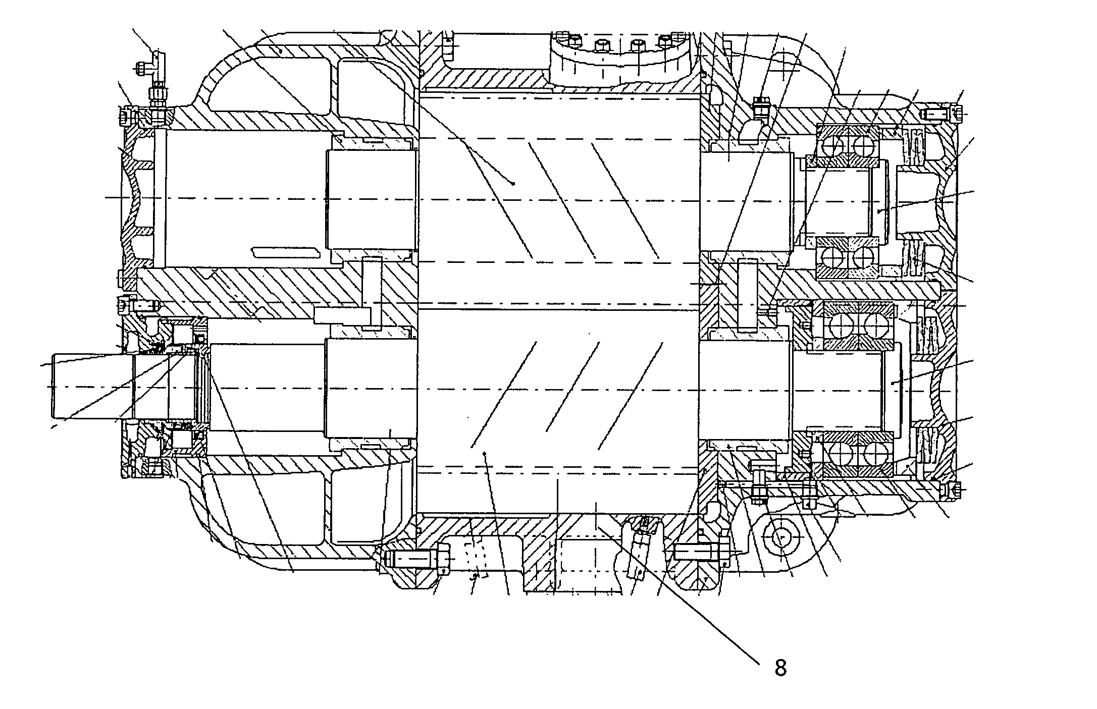
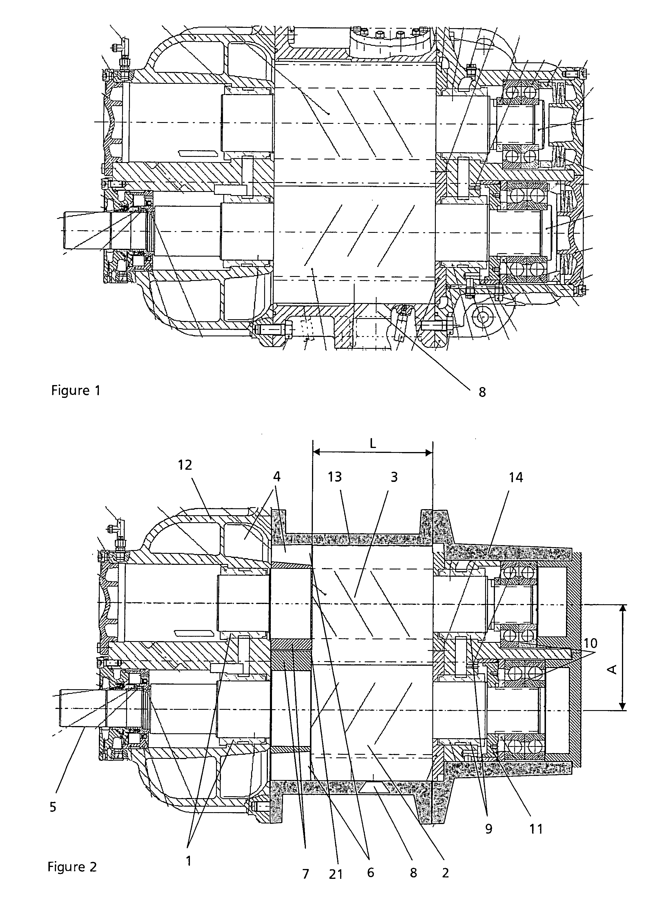
[0016]FIG. 1 a screw compressor of known design.

[0017]FIG. 2 a screw compressor according to the invention.

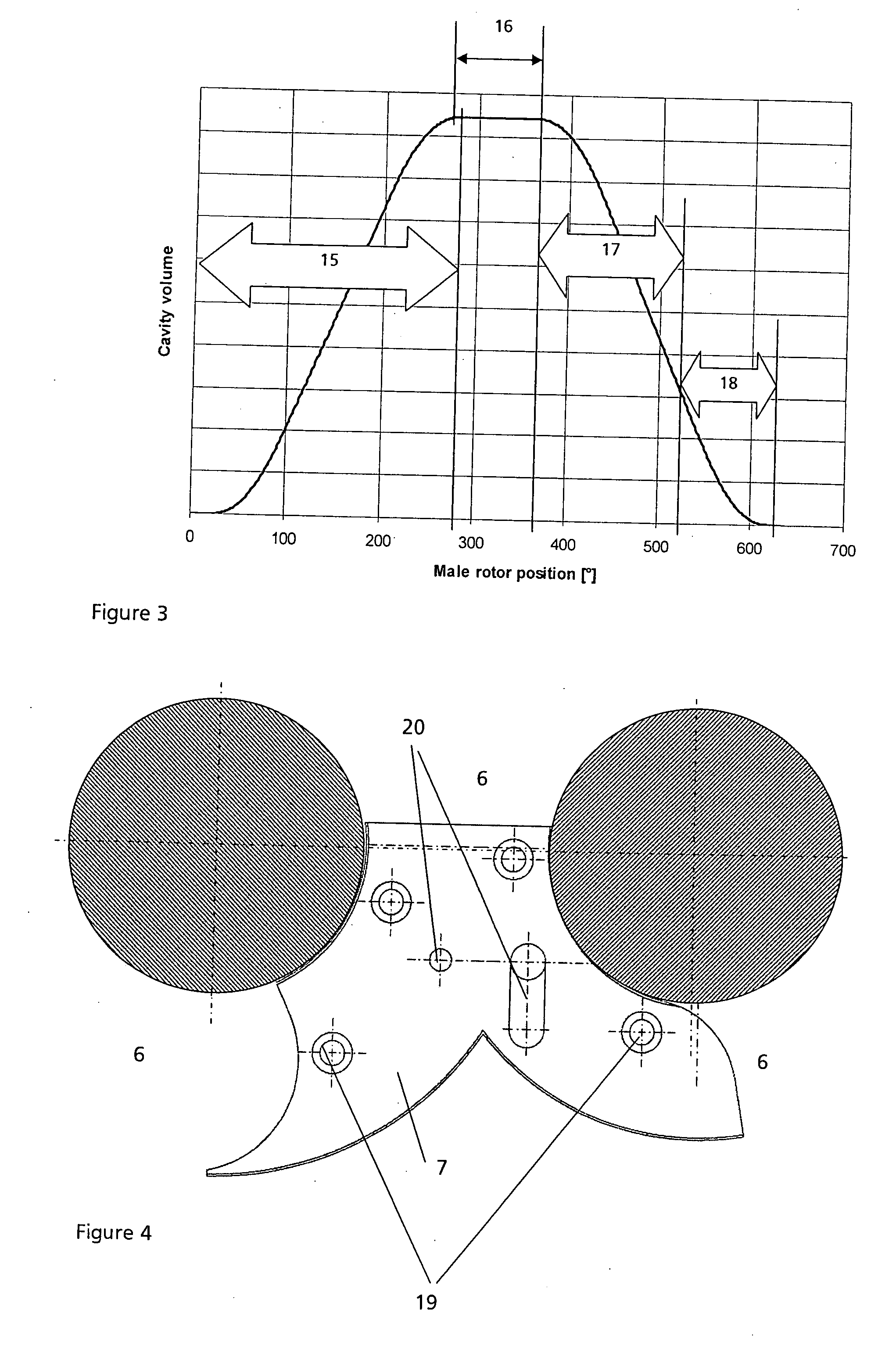
[0018]FIG. 3 the working cavity volume as a function of the male rotor position for a screw compressor according to the invention.

[0019]FIG. 4 an sample of an intermediate plate according the invention.

[0020]In the screw compressor according to the invention, the same components as in the case of the known compressor are used to a large extend. The compressor is driven via a coupling not shown at the drive-shaft end 5, which is a fixed part of the male rotor 2. The interlobe spaces of the five-lobe male rotor 2 the profile section of which has a wrap angle of 180° and of the six-lobe female rotor 3 the profile section of which has a wrap angle of 150°, form working cavities, to which adjoins according to the invention on the suction side in the rotor-housing section...


PUM


Abstract

The invention relates to oil-flooded screw compressors having a male rotor and female rotor each featuring preferably a ratio of male-to-female rotor lobes of 4:6, 5:6 or 5:7. In order to decrease the bearing load at higher working pressures, the profile sections of the rotors are shortened, and an intermediate plate is appropriately arranged in the free space formed.

Description

FIELD OF THE INVENTION[0001]The invention relates to oil-flooded screw compressors for high input power. Such screw compressors have two parallel rotors: a male rotor having essentially convex lobe flanks featuring four, five or six lobes, and a female rotor having essentially concave lobe flanks featuring six or seven lobes; the male rotor has a drive-shaft end and both rotors are enclosed in housing sections: a suction-housing section having at least parts of a suction channel and parts of an inlet port for passing of the working fluid into the interlobe spaces of the rotor pair, a rotor-housing section at least partially enclosing the profile section of the rotors, and a discharge housing having at least an outlet port for passing the gas out of the interlobe spaces of the rotor pair due to rotation of the rotors, and a discharge channel.[0002]Such screw compressors have a working space designated also as working chamber or working cavity formed by the interlobe spaces of both ro...

Claims


Application Information

Patent Timeline
IPC IPC(8): F01C1/16F01C1/24F03C2/00
CPCF04C18/084F04C29/0021F04C27/006F04C18/16F04C2210/22F04C2240/80
Inventor MOSEMANN, DIETERZAYTSEV, DMYTRONEUWIRTH, OTTOMAR
Owner GEA REFRIGERATION GERMANY
Why Eureka
Try Eureka