Information terminal device, radio communication system and radio communication method

a technology of information terminal and radio communication system, which is applied in the direction of power management, high-level techniques, wireless commuication services, etc., can solve the problems of reducing the number of transmitting times of the beacon signal accompanying considerable power consumption, increasing power consumption, and unable to say that power consumption is effectively made in radio communication between information terminals. achieve the effect of power saving more properly

Inactive Publication Date: 2007-11-15
KONICA MINOLTA INC
View PDF4 Cites 43 Cited by
  • Summary
  • Abstract
  • Description
  • Claims
  • Application Information

AI Technical Summary

Benefits of technology

[0010]According to the invention, the information terminal device having a display has: (a) a data communication unit capable of switching between an active state and an inactive state and performing radio data communication with another information terminal device; (b) a low-power communication unit capable of performing radio communication with the another information terminal device with power consumption smaller than that of the data communication unit; and (c) a controller which sets the data communication unit to the inactive state except for a communication process period in which process necessary for the data communication is performed. Start timing and/or end timing of the communication process period can be

Problems solved by technology

In particular, in the case of connecting information terminals in an ad-hoc mode by using a wireless LAN, it is necessary to transmit a beacon signal for recognizing the existence of a communicatable terminal, so that power consumption increases.
Consequent

Method used


Image

  • Information terminal device, radio communication system and radio communication method
  • Information terminal device, radio communication system and radio communication method
  • Information terminal device, radio communication system and radio communication method

Examples


Embodiment Construction

[0026]Outline of Information Terminal Device

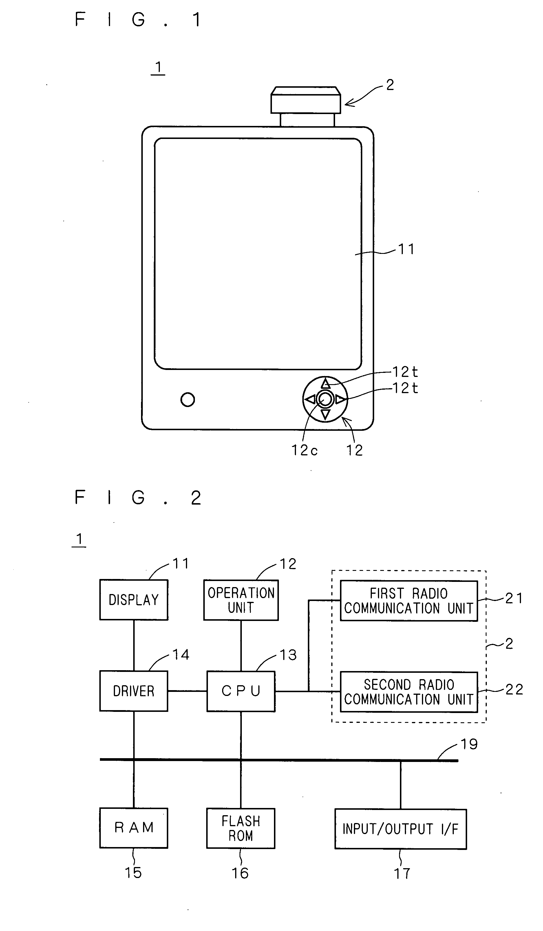
[0027]FIG. 1 is an appearance diagram showing the configuration of main components of an information terminal device 1 according to an embodiment of the invention, and is a front view of the information terminal device 1.

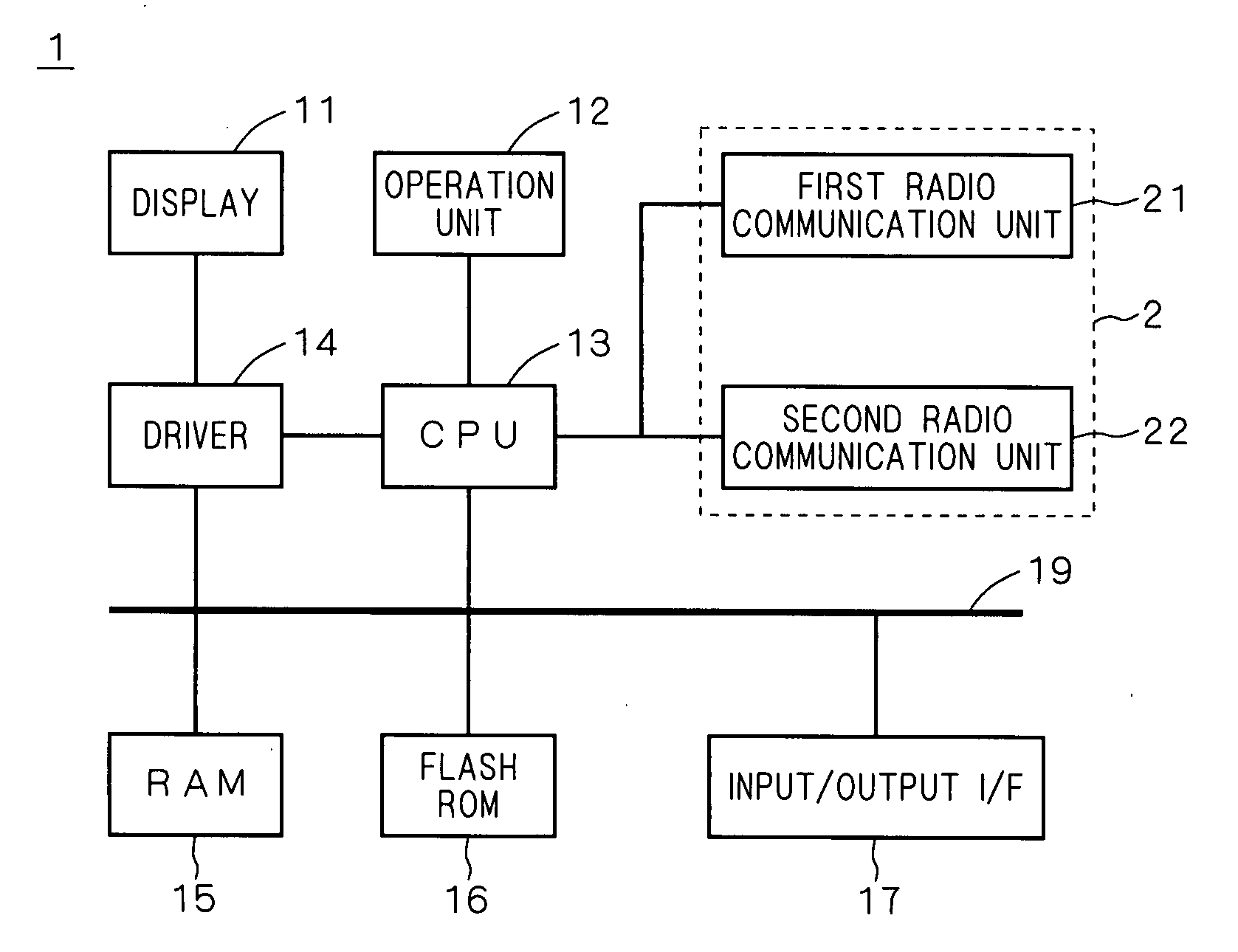
[0028]The information terminal device (hereinbelow, simply called “terminal”) 1 has a display 11, an operation unit 12, and a radio unit 2.

[0029]The display 11 can display image data and is constructed as a display device having a nonvolatile memory characteristic.

[0030]As the display device having a memory characteristic concerning a display (state), for example, a display device can be used having a ferroelectric liquid crystal display element, an anti-ferroelectric liquid crystal display element, a ferroelectric polymer liquid crystal display element, a cholesteric liquid crystal display element using chiral nematic liquid crystal showing a cholesteric liquid crystal phase at room temperature or the like, an electrochro...


PUM


Abstract

An information terminal device (terminal) has a first radio communication unit capable of performing radio communication with low power consumption and a second radio communication unit performing data communication using a wireless LAN. In an ad-hoc mode in which data communication is performed between the terminals, as a rule, the second radio communication unit is set in a sleep mode. However, when actual data communication is necessary, an activation signal is transmitted to a terminal as a communication party by using the first radio communication unit to activate the second radio communication unit. After completion of data communication, a stop signal is transmitted to the terminal as the communication party by using the first radio communication unit to stop the second radio communication unit on the transmission side. In such a manner, transmission of a beacon signal from the second radio communication unit is suppressed, and proper power saving is realized.

Description

[0001]This application is based on application No. 2006-131313 filed in Japan, the content of which is hereby incorporated by reference.BACKGROUND OF THE INVENTION[0002]1. Field of the Invention[0003]The present invention relates to the technique of an information terminal device having a display.[0004]2. Description of the Background Art[0005]In data communication of an information terminal device, as radio communication infrastructure develops, downloading of information via an access point such as a hot spot (radio spot) became possible also in a portable information terminal, and information terminals are connected by radio and share information.[0006]In the case where it is difficult to supply power from an external power supply at the time of performing radio communications in a portable information terminal, power is supplied from an internal power supply such as a built-in battery. In such a case, it is important to increase the life of the battery or the like by saving powe...

Claims


Application Information

Patent Timeline
IPC IPC(8): H04Q7/20H04W52/02H04W84/12H04W84/18H04W88/06
CPCH04M1/7253H04W52/0235Y02B60/50H04W84/18H04W88/06H04W84/12H04M1/72412Y02D30/70
Inventor HAMAGUCHI, TAKAYUKI
Owner KONICA MINOLTA INC
Why Eureka
Try Eureka