Fiber optic instrument sensing system

Inactive Publication Date: 2007-11-15
KONINKLIJKE PHILIPS ELECTRONICS NV
View PDF81 Cites 198 Cited by
  • Summary
  • Abstract
  • Description
  • Claims
  • Application Information

AI Technical Summary

Benefits of technology

[0007] In one embodiment, a medical instrument system comprises an elongate instrument body; an optical fiber coupled in a constrained manner to the elongate instrument body, the optical fiber including one or more Bragg gratings; a detector operably coupled to a proximal end of the optical fiber and configured to detect respecti

Problems solved by technology

Conventional technologies such as electromagnetic position sensors, available from providers such as the Biosense Webster division of Johnson & Johnson, Inc., or conventional thermocouples, available from providers such as Keithley Instrument

Method used


Image

  • Fiber optic instrument sensing system
  • Fiber optic instrument sensing system
  • Fiber optic instrument sensing system

Examples


Embodiment Construction

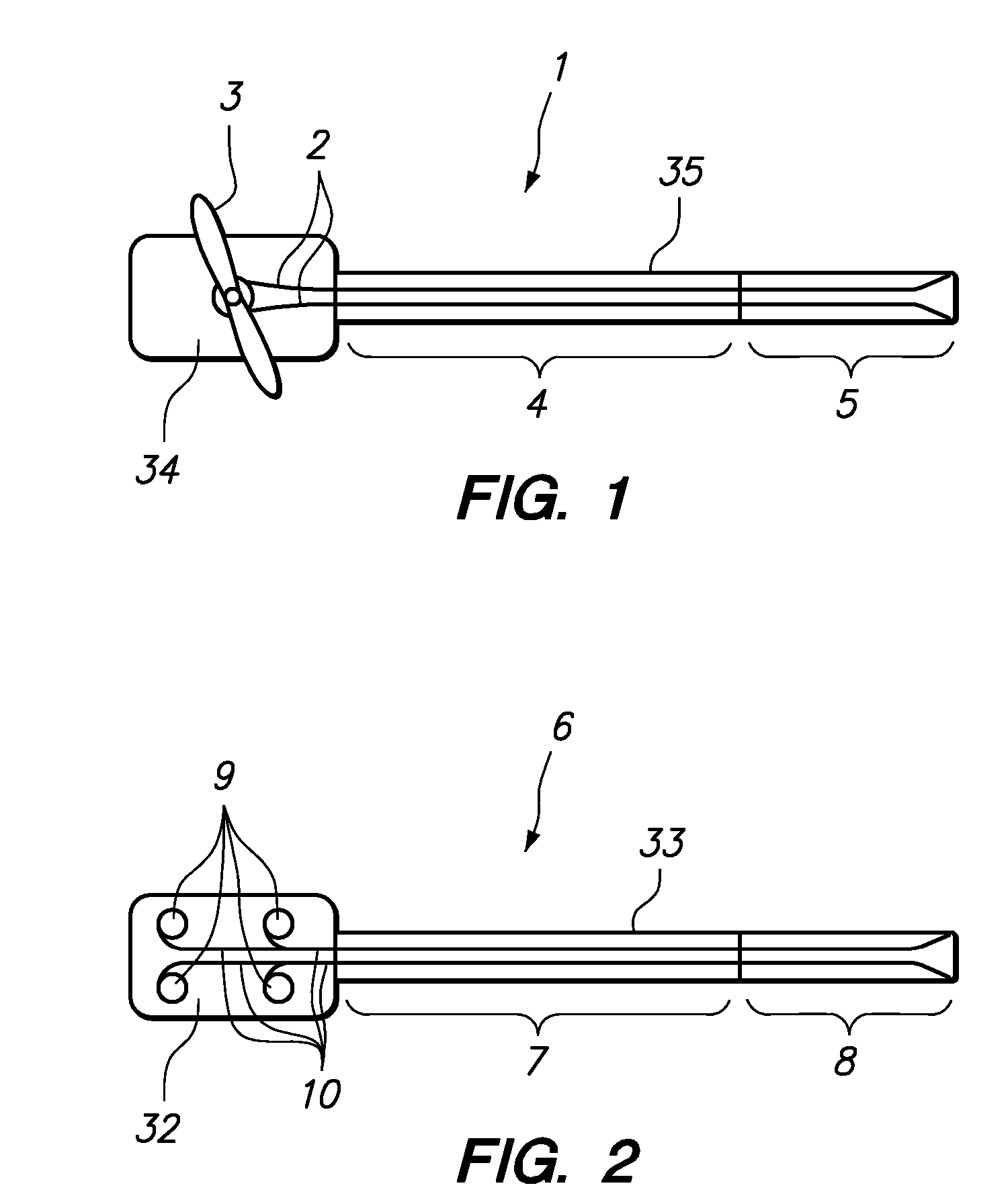
[0031] Referring to FIG. 1, a conventional manually-steerable catheter (1) is depicted. Pullwires (2) may be selectively tensioned through manipulation of a handle (3) on the proximal portion of the catheter structure to make a more flexible distal portion (5) of the catheter bend or steer controllably. The handle (3) may be coupled, rotatably or slidably, for example, to a proximal catheter structure (34) which may be configured to be held in the hand, and may be coupled to the elongate portion (35) of the catheter (1). A more proximal, and conventionally less steerable, portion (4) of the catheter may be configured to be compliant to loads from surrounding tissues (for example, to facilitate passing the catheter, including portions of the proximal portion, through tortuous pathways such as those formed by the blood vessels), yet less steerable as compared with the distal portion (5).

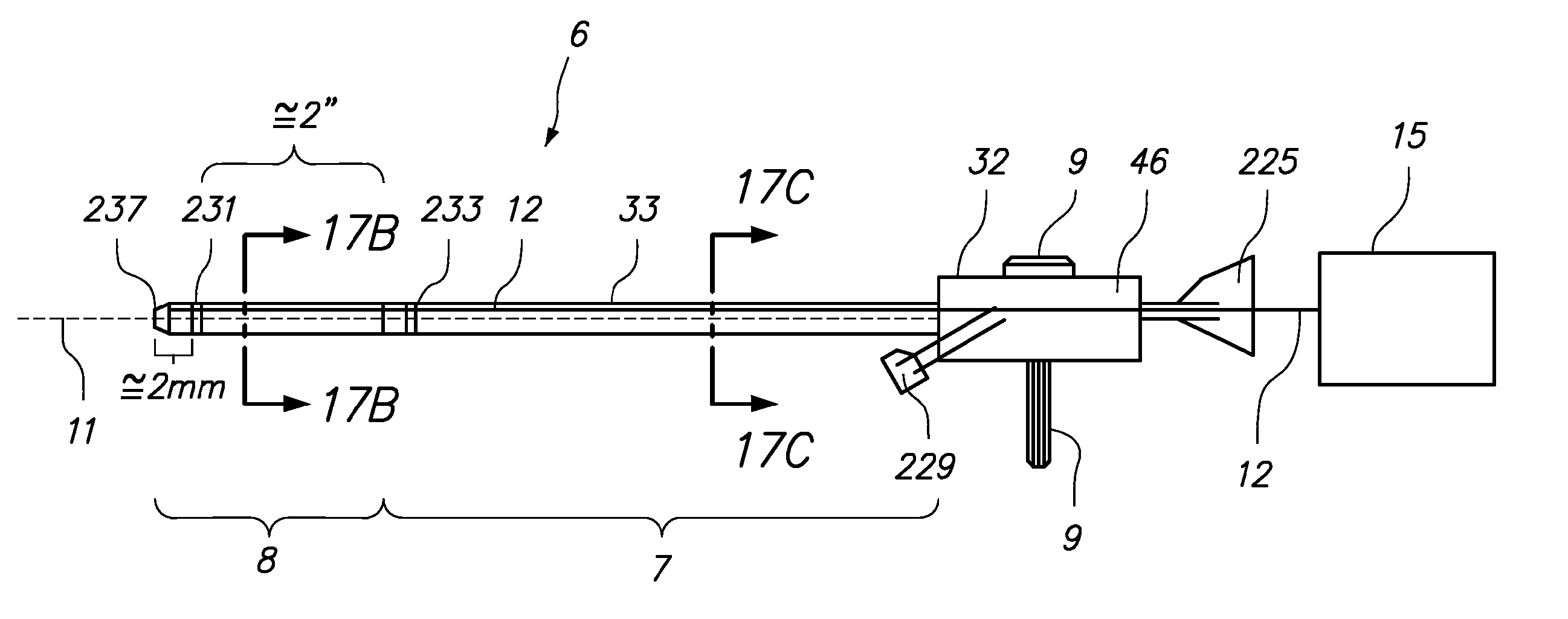
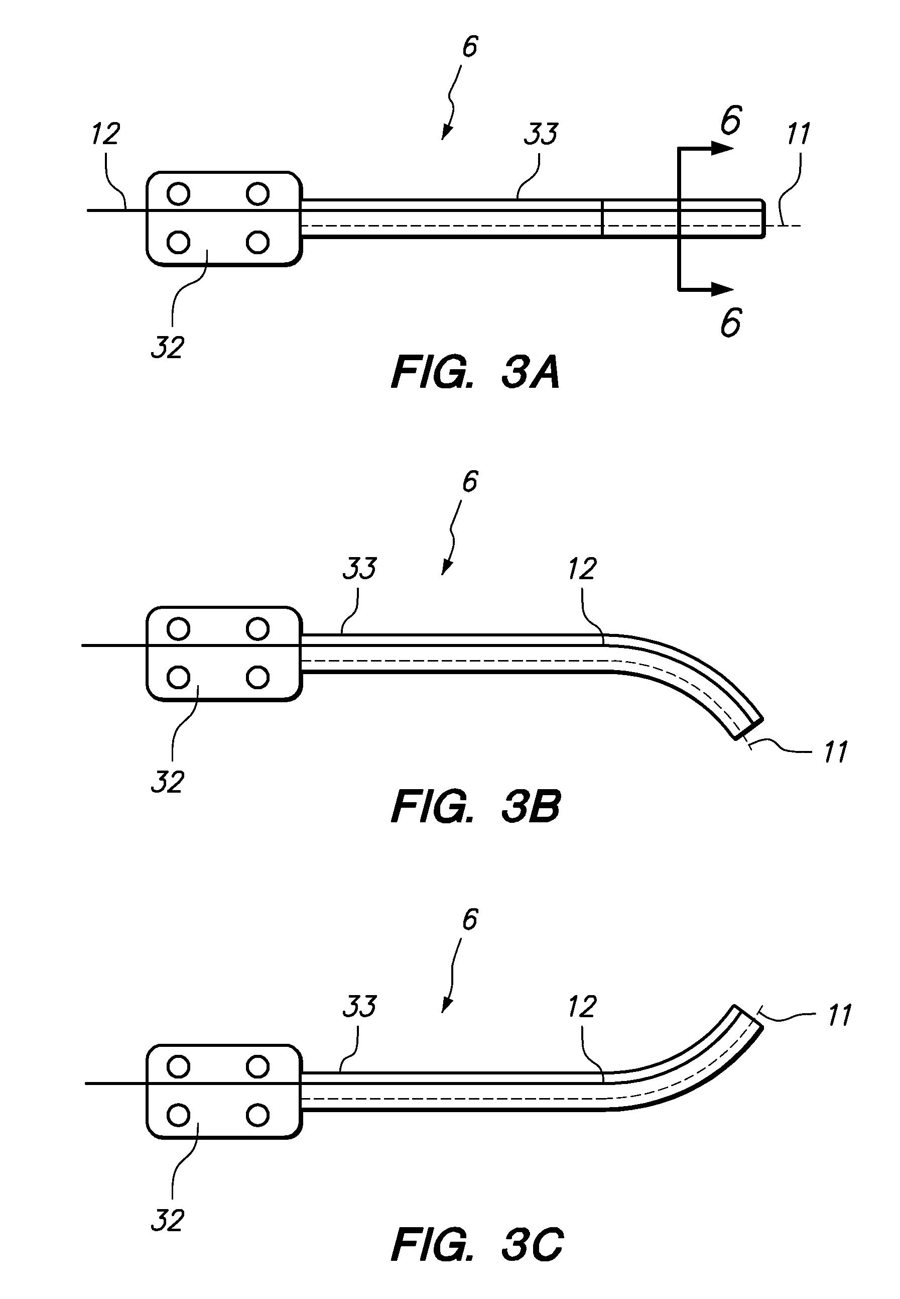
[0032] Referring to FIG. 2, a robotically-driven steerable catheter (6), similar to those describe...


PUM


Abstract

A medical instrument system comprises an elongate instrument body; an optical fiber coupled in a constrained manner to the elongate instrument body, the optical fiber including one or more Bragg gratings; a detector operably coupled to a proximal end of the optical fiber and configured to detect respective light signals reflected by the one or more Bragg gratings; and a controller operatively coupled to the detector, wherein the controller is configured to determine a geometric configuration of at least a portion of the elongate instrument body based on a spectral analysis of the detected reflected portions of the light signals.

Description

RELATED APPLICATION DATA [0001] The present application claims the benefit under 35 U.S.C. § 119 to U.S. provisional patent application Ser. Nos. 60 / 785,001, filed Mar. 22, 2006, and 60 / 788,176, filed Mar. 31, 2006. The foregoing applications are each hereby incorporated by reference into the present application in their entirety.FIELD OF INVENTION [0002] The invention relates generally to medical instruments, such as elongate steerable instruments for minimally-invasive intervention or diagnosis, and more particularly to a method, system, and apparatus for sensing or measuring the position and / or temperature at one or more distal positions along the elongate steerable medical instrument. BACKGROUND [0003] Currently known minimally invasive procedures for diagnosis and treatment of medical conditions use elongate instruments, such as catheters or more rigid arms or shafts, to approach and address various tissue structures within the body. For various reasons, it is highly valuable t...

Claims


Application Information

Patent Timeline
IPC IPC(8): A61B1/07
CPCA61B1/0055A61B5/065A61B2019/2211A61B2019/2296A61B2019/5261A61M25/0009G02B23/26A61M2025/0166G01D5/35303G02B6/02042G02B6/02057G02B6/02076A61M25/0147A61B2034/301A61B34/77A61B2034/2061G01D5/35354A61B1/009
Inventor SCHLESINGER, RANDALL L.KING, TOBY ST. JOHNLUNDMARK, DAVID
Owner KONINKLIJKE PHILIPS ELECTRONICS NV
Why Eureka
Try Eureka