
Position Estimation Apparatus, Position Estimation Method and Program Recording Medium

a position estimation and position estimation technology, applied in the direction of distance measurement, navigation instruments, instruments, etc., can solve the problems of inability to use the locus of the position detected by the sensor system, the non-robustness of the conventional self-estimation system adopting the algorithm of the kalman filter, and the locus observed from the correct estimated valu

Inactive Publication Date: 2007-11-15
SONY CORP
View PDF1 Cites 41 Cited by
  • Summary
  • Abstract
  • Description
  • Claims
  • Application Information

AI Technical Summary

Benefits of technology

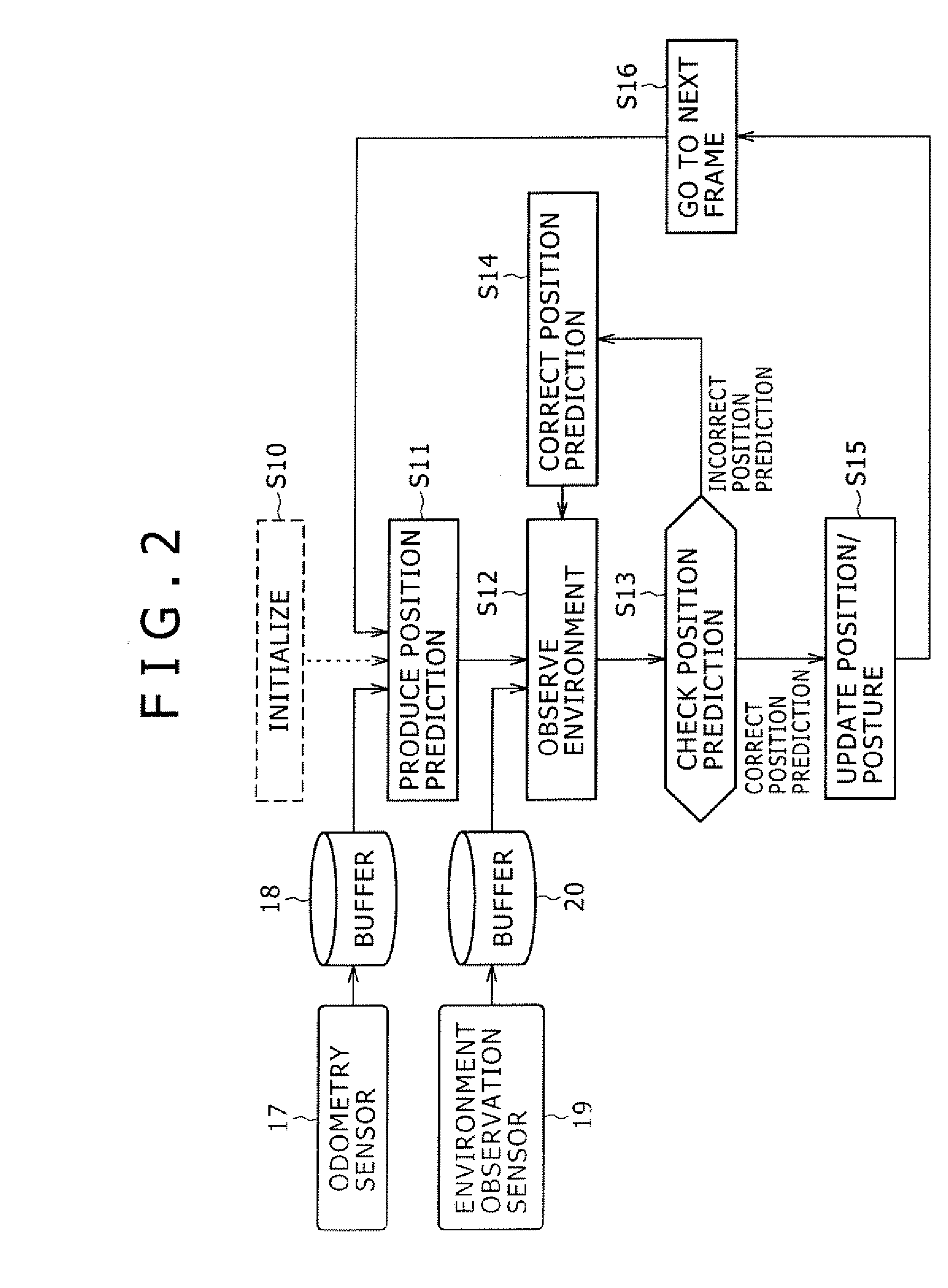
[0030] In accordance with the present invention, an estimated value is examined in order to produce a result of determination as to whether or not the estimated value deviates from the actual value, and a recovery to correct the estimated value is tried if the result of the determination indicates that the estimated value deviates from the actual value. Thus, if the result of the determination indicates that the estimated value deviates from the actual value, a locus traced for the positions detected by a sensor system as a locus ending with the most recent position can be reflected by correction of the estimated positions detected by the sensor system in a recovery process. As a result, the present invention provides a robust position estimation system.

Problems solved by technology

Thus, the conventional self estimation system adopting the algorithm of the Kalman filter is not robust.
This is because the locus observed from correct estimated values as the locus of the position detected by the sensor system is not usable in case the present estimation is determined to be incorrect.

Method used


Image

  • Position Estimation Apparatus, Position Estimation Method and Program Recording Medium
  • Position Estimation Apparatus, Position Estimation Method and Program Recording Medium
  • Position Estimation Apparatus, Position Estimation Method and Program Recording Medium

Examples


Embodiment Construction

[0040] A preferred embodiment of the present invention is described by referring to diagrams as follows.

[0041] The following description begins with explanation of an embodiment implementing a position estimation apparatus 10 provided for a mobile object (such as a robot) placed in a condition of a fixed (unchanging) environment. The mobile object employs an odometry sensor and a vision sensor, which are mounted on the mobile object itself, and the position estimation apparatus 10 uses values generated by the odometry sensor and the vision sensor.

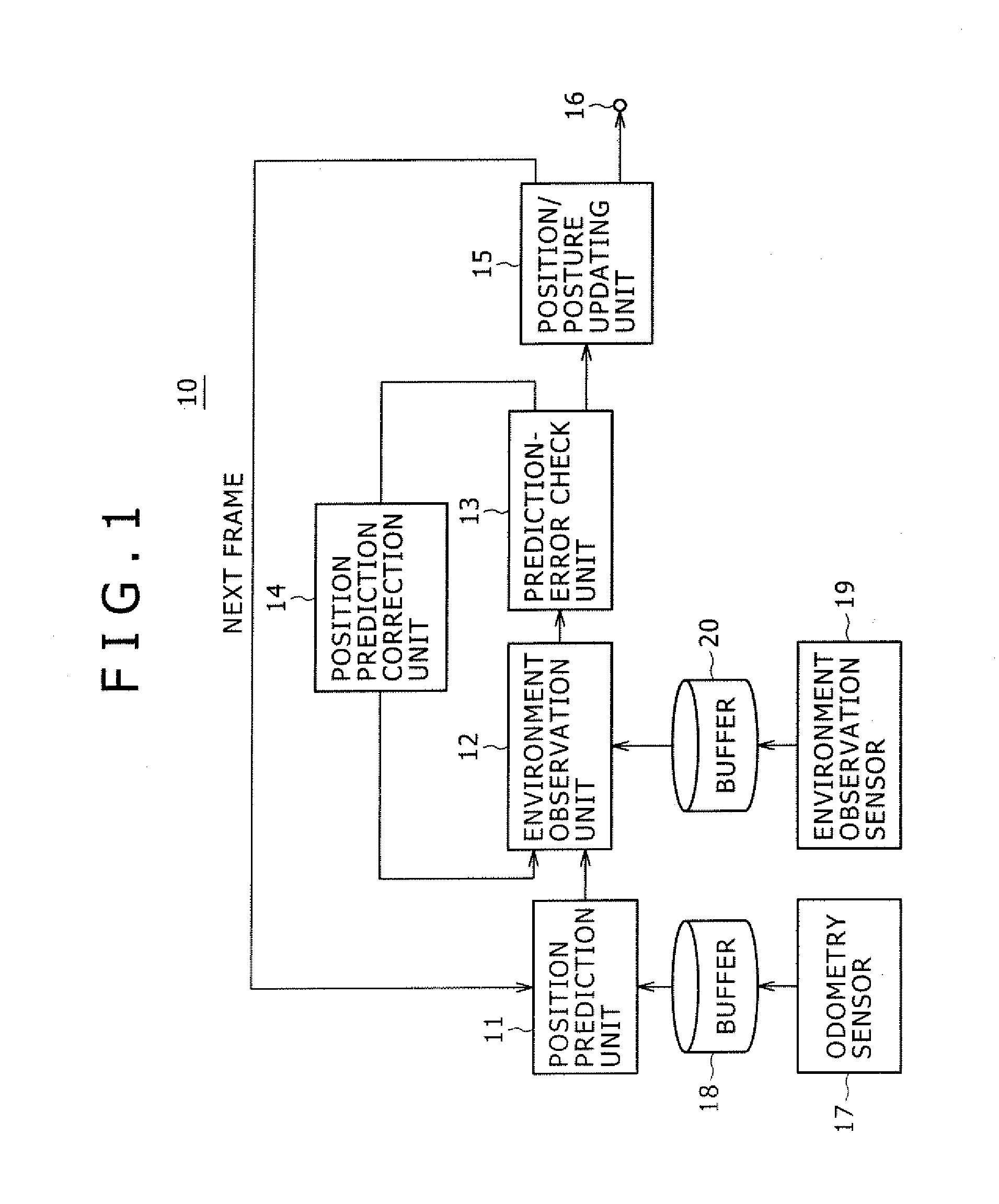
[0042]FIG. 1 is a block diagram showing the functional configuration of the position estimation apparatus 10. To put it concretely, the configuration of hardware employed in the position estimation apparatus 10 includes a CPU, a RAM, a ROM, an HDD and a variety of sensors mounted on the mobile object. The CPU, the RAM, the ROM and the HDD are connected to each other by a bus. In the functional block diagram shown in FIG. 1, the CPU loads ...


PUM


Abstract

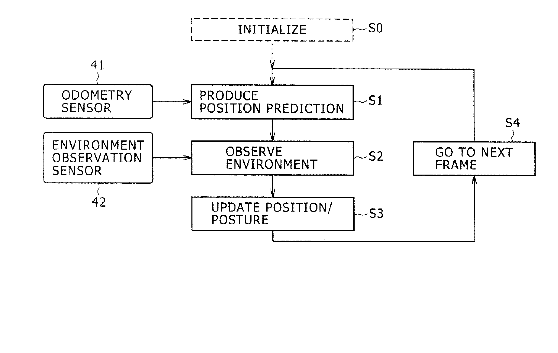
The present invention provides a position estimation apparatus capable of determining whether an estimated value deviates from an actual value and trying a process to correct the estimated value if the estimated value is determined to be incorrect. The position estimation apparatus employs a position prediction unit configured to produce a prediction of the position of a mobile object having an odometry sensor mounted thereon, an environment observation unit configured to keep track of each feature point in the environment of the mobile object, a prediction-error check unit configured to determine whether the position prediction produced by the position prediction unit is correct or incorrect, a position-prediction correction unit configured to correct a wrong position prediction and a position / posture updating unit configured to update the position and / or posture of the mobile object on the basis of a correct position prediction.

Description

CROSS REFERENCES TO RELATED APPLICATIONS [0001] The present invention contains subject matter related to Japanese Patent Application JP 2006-130602 filed in the Japan Patent Office on May 9, 2006, the entire contents of which being incorporated herein by reference. BACKGROUND OF THE INVENTION [0002] 1. Field of the Invention [0003] The present invention relates to a position estimation apparatus for estimating the position of a mobile object having a sensor such as a camera mounted thereon, as well as relates to a position estimation method to be adopted in the position estimation apparatus and a program recording medium used for recording a position estimation program implementing the position estimation method. [0004] 2. Description of the Related Art In a mobile object having a group of sensors mounted thereon as sensors of 2 types, i.e., odometry sensors such as an acceleration sensor and a velocity sensor and image-taking sensors such as a distance sensor, the position and post...

Claims


Application Information

Patent Timeline
Patent Type & Authority Applications(United States)
IPC IPC(8): G06F17/10
CPCG01C22/02G01C21/12
Inventor OI, KENICHIROFUJITA, MASAHIROYOSHIGAHARA, TAKAYUKIGUTMANN, STEFFENFUKUCHI, MASAKI
Owner SONY CORP
Learn More