Apparatus and method for measuring soil gases
- Summary
- Abstract
- Description
- Claims
- Application Information
AI Technical Summary
Benefits of technology
Problems solved by technology
Method used
Image
Examples
Embodiment Construction
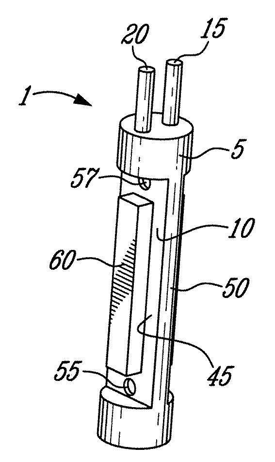
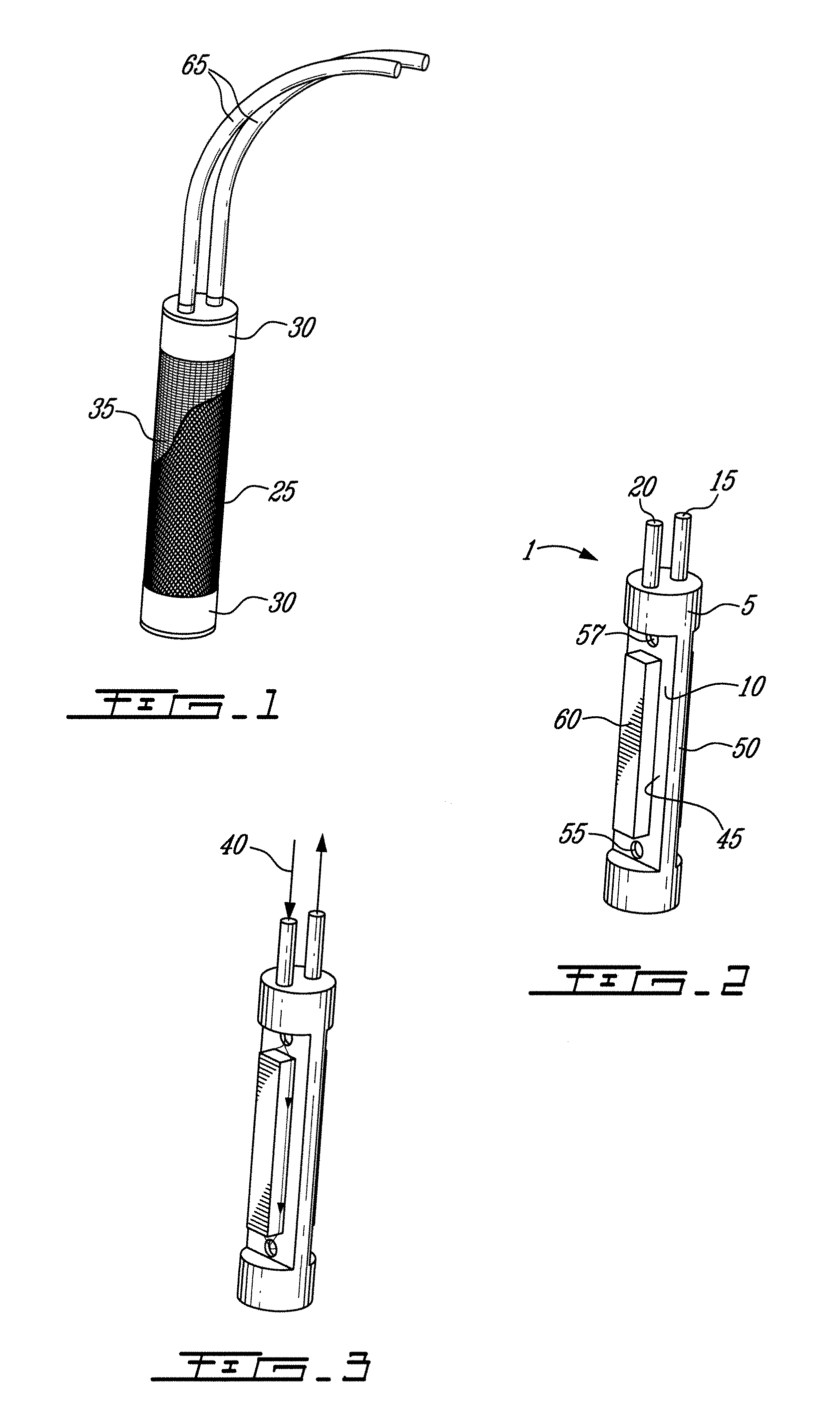
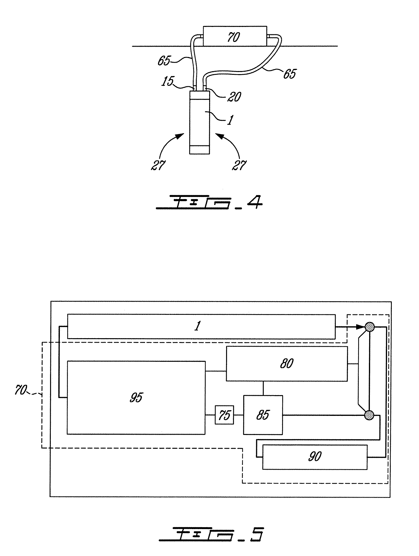
[0025]FIGS. 1 to 3 show a probe 1 intended to be buried more or less permanently in a soil gas measurement site. The probe comprises a body 5 having a cavity 10. Connected to the cavity 10 are an inlet 15 and an outlet 20. FIG. 2 shows a waterproof, microporous gas permeable membrane 25 wrapped around the body 5 and sealed with sealing means such as a sealing tape 30, for example. The membrane 25 seals the cavity 10 such that in use, soil gases 27 have to diffuse through the membrane 25 into the cavity 10. The membrane 25 may be bonded to the body 5. The cavity 10 contains a volume of air protected by the membrane 25 whose specific characteristics are selected to suit the application, in particular the required water column waterproofness, while maximizing diffusive potential.
[0026]The body 5 itself may be manufactured from metal or plastic. The membrane is covered with a tight-fitting fine stainless steel mesh 35 (partially shown) to help retain the shape of the membrane 25 against...
PUM
 Abstract
Description
Claims
Application Information
 - R&D
- Intellectual Property
- Life Sciences
- Materials
- Tech Scout
- Unparalleled Data Quality
- Higher Quality Content
- 60% Fewer Hallucinations
Browse by: Latest US Patents, China's latest patents, Technical Efficacy Thesaurus, Application Domain, Technology Topic, Popular Technical Reports.
© 2025 PatSnap. All rights reserved.Legal|Privacy policy|Modern Slavery Act Transparency Statement|Sitemap|About US| Contact US: help@patsnap.com


