Method and apparatus for wind power foundation

a wind power plant and foundation technology, applied in mechanical equipment, machines/engines, other chemical processes, etc., can solve the problems of large amount of real estate for wind power conventionally required and more complex environment for plant construction

Inactive Publication Date: 2007-11-22
GENERAL ELECTRIC CO
View PDF6 Cites 47 Cited by
  • Summary
  • Abstract
  • Description
  • Claims
  • Application Information

AI Technical Summary

Problems solved by technology

For all of the benefits of wind power, it is clear that wind power conventionally requires a large amount of real estate for placement of plants.
In addition to creating greater forces in operation, the placement of wind power plants farther off-shore creates a more complex environment for plant construction, with much of the plant foundation being deep underwater.

Method used


Image

  • Method and apparatus for wind power foundation
  • Method and apparatus for wind power foundation
  • Method and apparatus for wind power foundation

Examples


first embodiment

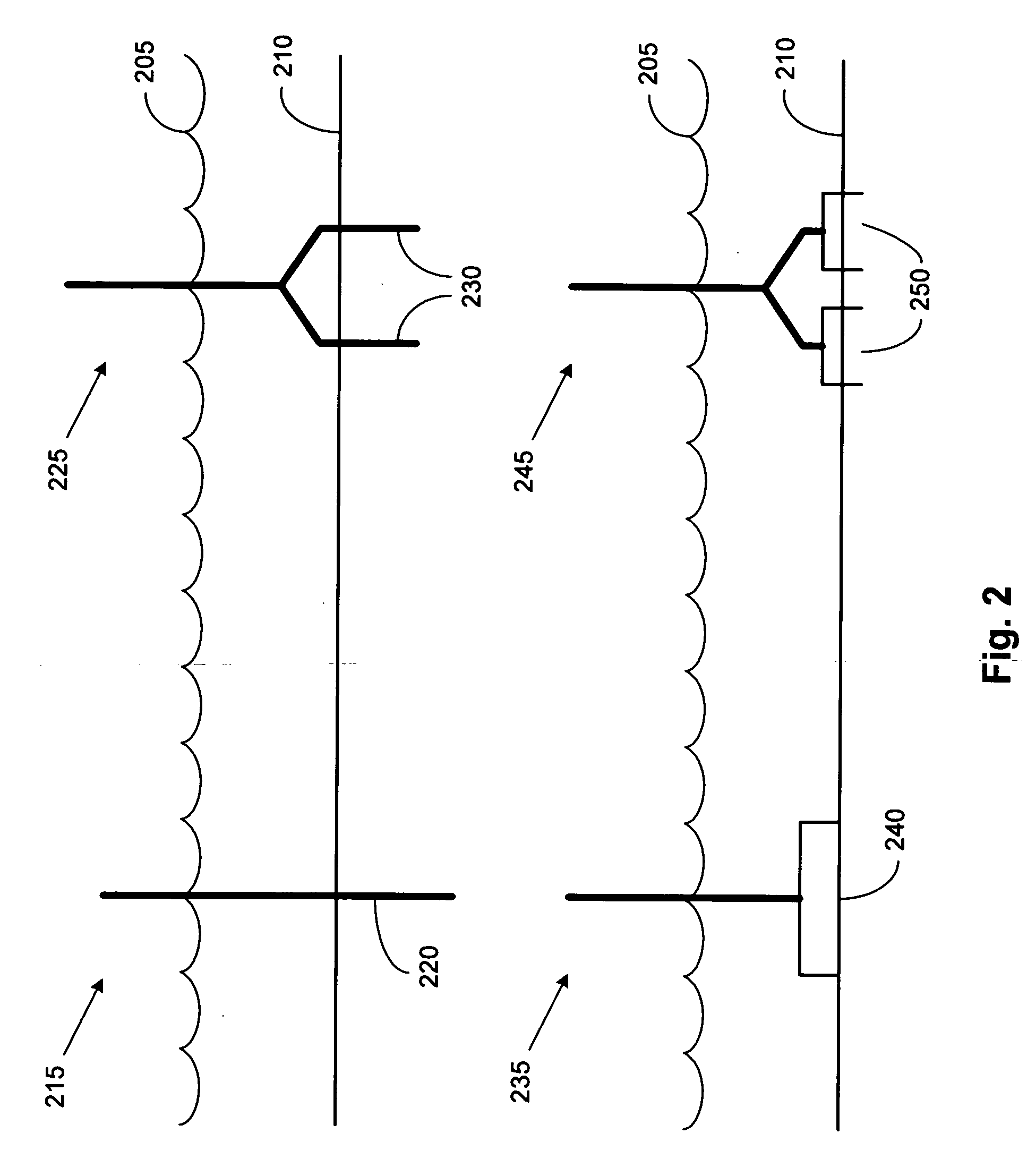
[0029]In a first embodiment, a jacket structure supporting a wind turbine plant is secured by one more piles driven through the legs of the jacket structure into the earth surface. In this embodiment, the legs of the jacket structure are hollow sleeves, such as pipe-like structures, through which a pile may be inserted. The jacket structure may be placed in the appropriate location for the wind turbine plant, with the piles inserted through the leg sleeves of the jacket structure and driven into the earth.

second embodiment

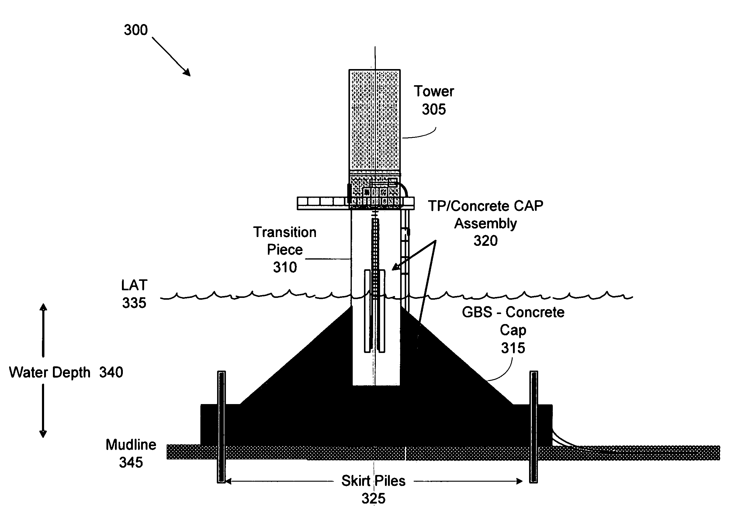
[0030]In a second embodiment, a jacket structure supporting a wind turbine plant is secured by a concrete pad or similar gravity base. The concrete pad may be referred to as a gravity base structure (GBS). A GBS secures a structure using the mass of the base structure. In an embodiment, the bottom portions of the legs of the jacket are run at least partially through the GBS. The legs of the jacket may be secured by a flanged connection, each leg running through the flange into the GBS.

third embodiment

[0031]In a third embodiment, a jacket structure supporting a wind turbine plant may be secured by multiple concrete pads or GBSs. For example, the bottom portion of each leg of the jacket may run partially or wholly through a concrete pad. Each leg may be secured by a flanged connection, the leg running through the flange into the concrete pad.

[0032]In an embodiment of the invention, the load transfer of a wind power turbine is modified to increase the strength and resiliency of a base structure. In certain types of structures, a load on a tower is transferred to a concrete section, and then is transferred directly to the soil. While the concrete cap may provide a good physical connection to the tower, the concrete cap may not effectively transfer the load to the soil, and may create concentrations of stress in the structure. In another example, a wind turbine supported by a jacket structure may better transfer load forces, but the jacket does not provide an optimal coupling with th...


PUM


Abstract

An apparatus and method for a wind power foundation. An embodiment of a wind power plant includes a tower having a top and a bottom. The plant also includes an assembly, the assembly including a transition piece that is coupled with a concrete cap. The assembly has a top and a bottom, with the top of the assembly being coupled with the bottom of the tower. The plant also includes a jacket structure. The jacket structure has a top and a bottom and multiple legs, with the bottom of the assembly being coupled with the top of the jacket structure.

Description

FIELD OF THE INVENTION[0001]The invention relates to wind power plants in general. More particularly, the invention relates to a foundation for a wind power plant.BACKGROUND[0002]Wind power continues to grow as a source of electricity because of its potential to provide abundant, pollution-free power. Demand for this alternative energy source is expected to increase because of concerns regarding reductions in fossil fuel supplies, the impact of traditional energy sources on the environment, and the increasing need for electric power throughout the world.[0003]As the use of wind power increases, more questions have arisen regarding the placement of wind power plants. For all of the benefits of wind power, it is clear that wind power conventionally requires a large amount of real estate for placement of plants. As an alternative to land-based wind power generation, wind power plants have been placed offshore in ocean waters, thereby making use of offshore winds while not requiring any...

Claims


Application Information

Patent Timeline
Patent Type & Authority Applications(United States)
IPC IPC(8): E21B17/01
CPCE02B2017/0065E02B2017/0091E02D27/42E02D27/52F03D11/045Y10S415/908F05B2240/95Y02E10/727Y02E10/728Y10S416/06F05B2240/9121E02B17/0004E02D27/425F03D13/22Y02E10/72
Inventor KOTHNUR, VASANTH SRINIVASSANDERSON, DAVID DELOYD
Owner GENERAL ELECTRIC CO
Why Eureka
Try Eureka