Methods and apparatus for constant-power loading for asymmetric antenna configuration

a technology of asymmetric antennas and constant power loading, applied in the field of data communication, can solve the problems of high cost due to receiver complexity, only working well, and requiring auto-detection

Inactive Publication Date: 2007-11-22
SAMSUNG ELECTRONICS CO LTD
View PDF29 Cites 46 Cited by
  • Summary
  • Abstract
  • Description
  • Claims
  • Application Information

AI Technical Summary

Benefits of technology

[0008] In one embodiment, the present invention provides a method and system for constant-power loading for asymmetric antenna configurations. The sounding packet, the sounding bit in HT-SIG field, and the HT-LTF field in the PLCP protocol data unit (PPDU) are used to determine the number of transmit antennas (Ntx) and the number of data streams (Nss), wherein if Ntx=Nss, then a first ...

Problems solved by technology

Such methods are robust for different antenna configurations, channel condition etc., but result in higher cost due to receiver complexity (auto-detection is required).
However, such an approach only works well when trans...

Method used


Image

  • Methods and apparatus for constant-power loading for asymmetric antenna configuration
  • Methods and apparatus for constant-power loading for asymmetric antenna configuration
  • Methods and apparatus for constant-power loading for asymmetric antenna configuration

Examples


first embodiment

[0026] In the first example implementation according to the present invention, antenna information is based on the beamforming protocol, where sounding is performed before the start of the beamforming transmission.

[0027] In the following description AP represents a WLAN access point, and STA represents a WLAN client. In general, as shown by example in FIG. 4, the beamforming protocol includes a Calibration Protocol 401 and a Beamforming Transmission Protocol 402. The AP needs to be calibrated first before any beamforming transmission. The details of the Calibration Protocol 401 are diagrammatically shown by example in the event diagram 500 of FIG. 5 between an AP and an STA, wherein first, the AP sends a request for calibration to the STA. Then, the STA performs calibration training and send sounding packet to the AP. Then, the AP estimates the unlink channel, performs calibration training and sends a sounding packet to the STA. The, STA estimates the downlink channel and sends the...

second embodiment

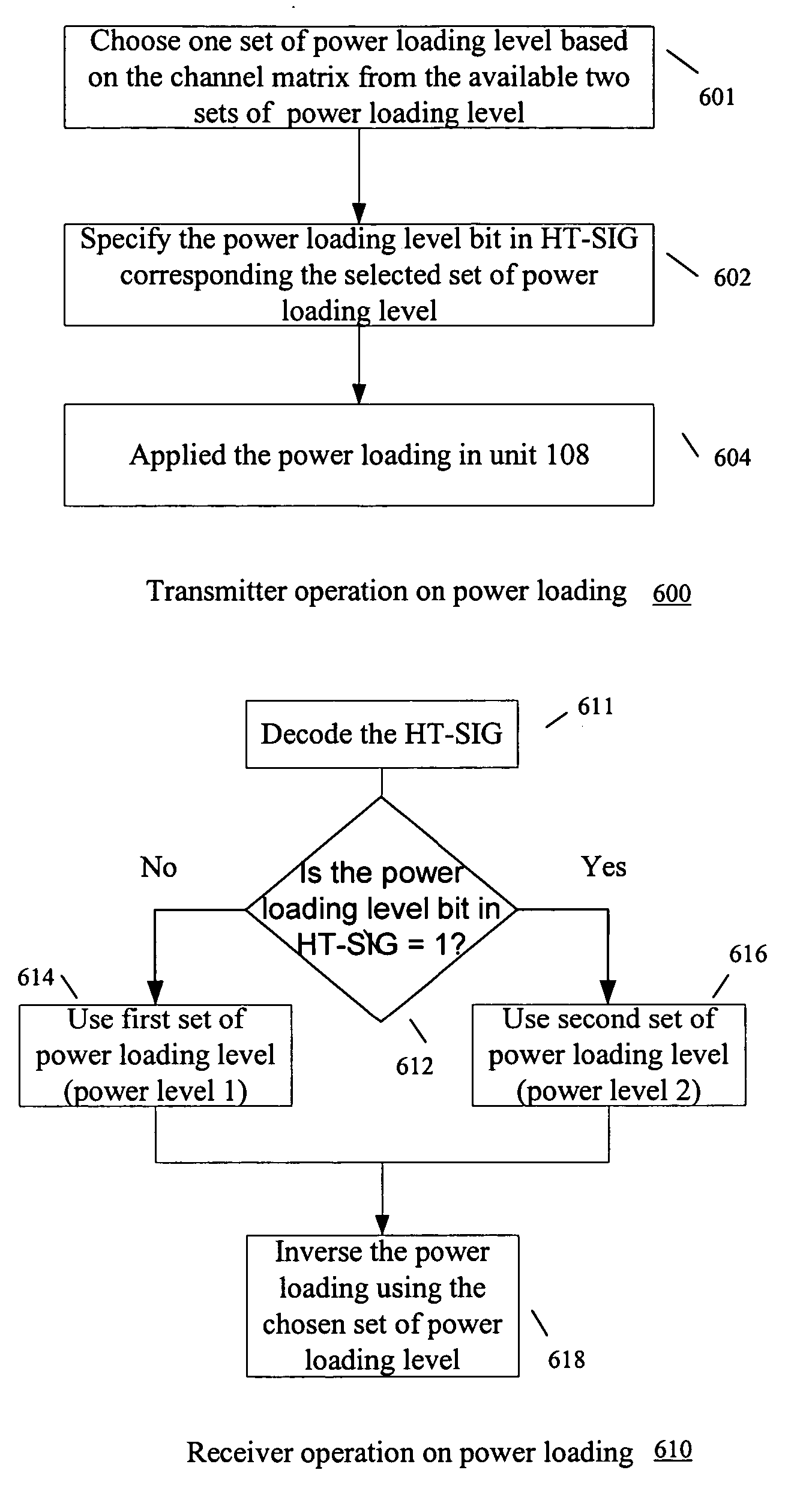
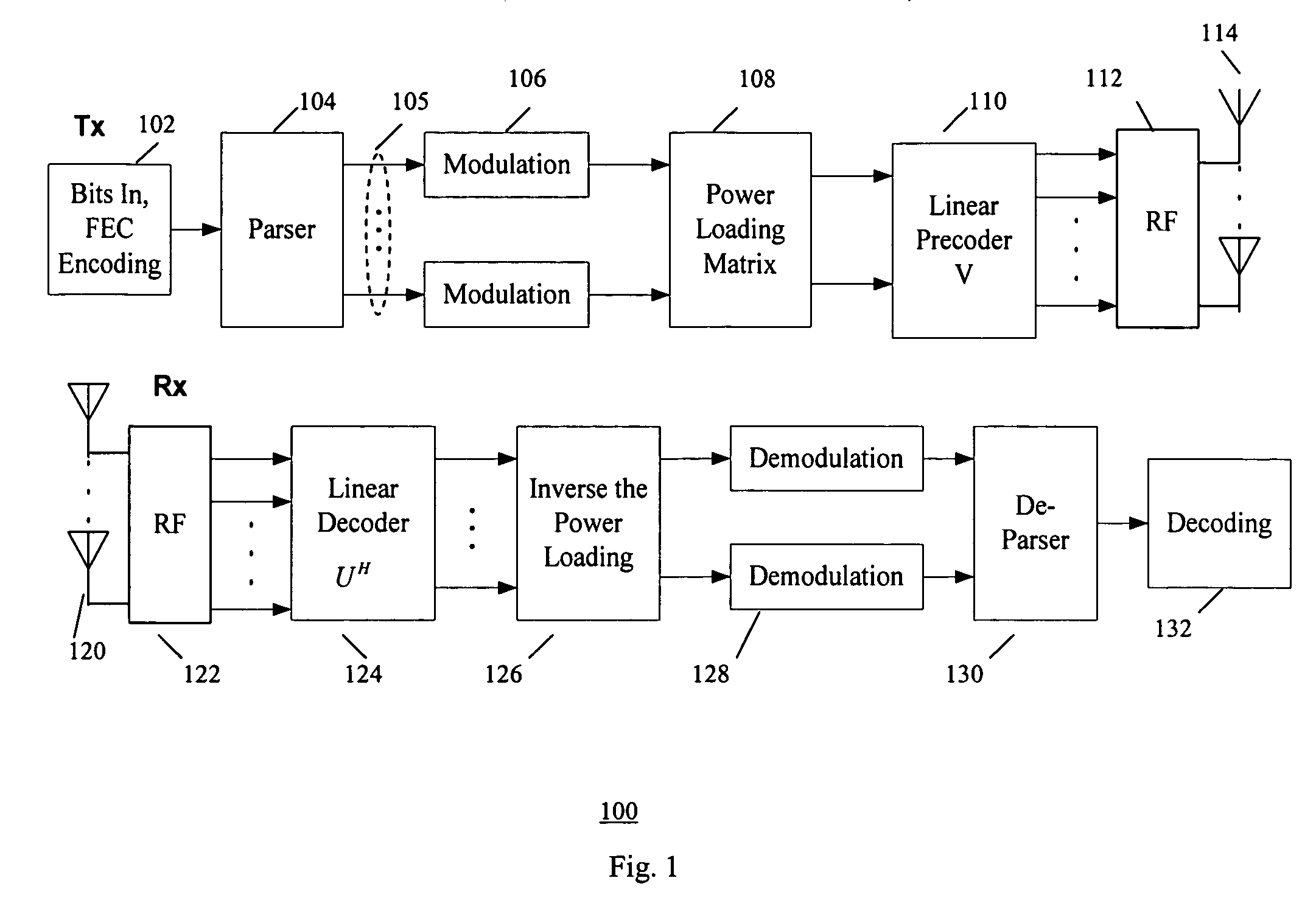
[0034] In the second example implementation according to the present invention, the power level information is obtained using an extra bit in the signaling field. FIG. 6 shows flowchart 600 of example steps 601-604 for transmitter operation on power loading, and example flowchart 610 of steps 611-618 for receiver operation on power loading. The power level information is obtained using an extra bit in the signaling field (i.e., extra bit in the HT-SIG field of PLCP protocol data unit (PPDU)), wherein if the extra bit is 0, a first set of power loading level is used (e.g., power level 1), and if the extra bit is 1, then a second set of power loading level (e.g., power level 2) is used.

[0035] The codebook of the power level is redesigned such as described by example in the above-mentioned commonly assigned patent applications. The selection of power level is signaled in the HT-SIG field. In one example, a codebook with “0” is utilized to represent the first set of power loading (e.g....


PUM


Abstract

A method and system for constant-power loading for asymmetric antenna configurations. The sounding packet, the sounding bit in HT-SIG field, and the HT-LTF field in the PLCP protocol data unit (PPDU) are used to determine the number of transmit antennas and the number of data streams, wherein if the number of transmission streams is the same as the number of data streams, then a first set of power loading level (fixed uneven power loading) is applied, otherwise a second set of power loading level is applied. Alternatively, one additional bit in the HT-SIG filed of PLCP protocol data unit (PPDU) signaling field is used to signal the set of power loading level used.

Description

FIELD OF THE INVENTION [0001] The present invention relates generally to data communication, and more particularly, to data communication in multi-channel communication system such as multiple-input multiple-output (MIMO) systems. BACKGROUND OF THE INVENTION [0002] A multiple-input-multiple-output (MIMO) communication system employs multiple transmit antennas in a transmitter and multiple receive antennas in a receiver for data transmission. A MIMO channel formed by the transmit and receive antennas may be decomposed into independent channels, wherein each channel is a spatial sub-channel (or a transmission channel) of the MIMO channel and corresponds to a dimension. The MIMO system can provide improved performance (e.g., increased transmission capacity) if the additional dimensionalities created by the multiple transmit and receive antennas are utilized. [0003] MIMO increases system link robustness and spectral efficiency. To optimize spectral efficiency for MIMO system, many effor...

Claims


Application Information

Patent Timeline
IPC IPC(8): H04B7/00
CPCH04B7/0413H04W52/346H04B7/0617H04B7/0443
Inventor NIU, HUANINGHORNG, JYHNGO, CHIU
Owner SAMSUNG ELECTRONICS CO LTD
Why Eureka
Try Eureka