Flow sensor with conditioning-coefficient memory
- Summary
- Abstract
- Description
- Claims
- Application Information
AI Technical Summary
Benefits of technology
Problems solved by technology
Method used
Image

Examples
Embodiment Construction
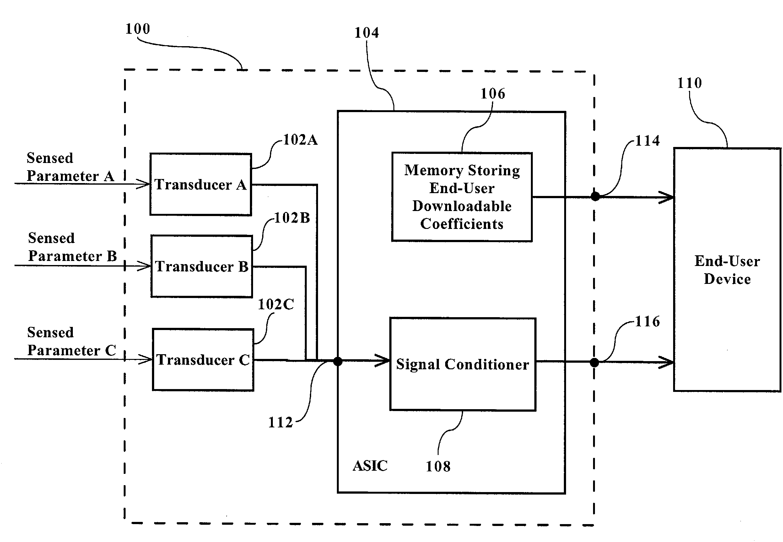
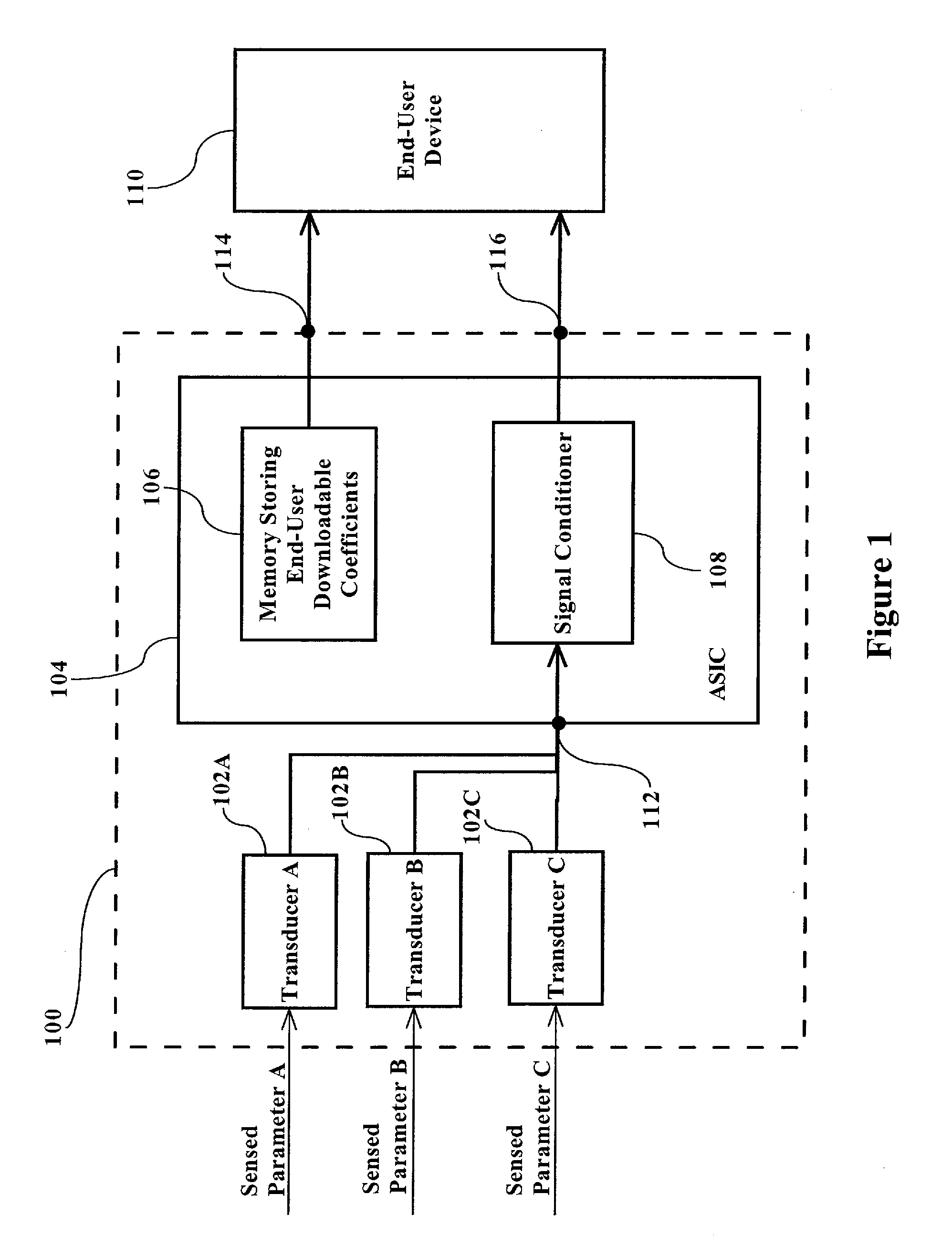
[0012]FIG. 1 is a block diagram illustrating the basic structure and concept of a preferred embodiment of the present invention. Referring to FIG. 1, a sensor 100 includes multiple sensor transducers 102A, 102B, and 102C each outputting a raw signal to an input 112 of a signal conditioner 108 of an ASIC 104. Although three sensor transducers are illustrated in FIG. 1, it is understood that any number of transducers can be utilized and still fall within the scope of the claimed invention. The raw signals correspond to a parameter sensed by sensor transducer 102A, 102B, and / or 102C. Signal conditioner 108 conditions the raw signals from sensor transducers 102A, 102B, and 102C in a well-known manner, using lower-order polynomial expressions (e.g., 2nd order or lower) to produce a coarsely-conditioned signal which is output, in this example, to end-user device 110 via an output 116.
[0013]Sensor transducers 102A, 102B, and 102C can each be any kind of sensor transducer, for example, sens...
PUM
 Abstract
Description
Claims
Application Information
 - Generate Ideas
- Intellectual Property
- Life Sciences
- Materials
- Tech Scout
- Unparalleled Data Quality
- Higher Quality Content
- 60% Fewer Hallucinations
Browse by: Latest US Patents, China's latest patents, Technical Efficacy Thesaurus, Application Domain, Technology Topic, Popular Technical Reports.
© 2025 PatSnap. All rights reserved.Legal|Privacy policy|Modern Slavery Act Transparency Statement|Sitemap|About US| Contact US: help@patsnap.com