Supercharge Your Innovation With Domain-Expert AI Agents!

Audio Encoder

a technology of encoder and encoder, applied in the field of encoder, can solve the problems of conventional compression methods, and achieve the effects of high practical value of the present invention, good sound quality, and easy reproduction

Active Publication Date: 2007-11-22
PANASONIC CORP
View PDF4 Cites 26 Cited by
  • Summary
  • Abstract
  • Description
  • Claims
  • Application Information

AI Technical Summary

Benefits of technology

[0013] As is clear from the above-mentioned description, the audio encoder of the present invention can encode multiple-channels so that a downmixed signal alone is to be decoded and can specifically create auxiliary information necessary for dividing the downmixed signal.
[0014] Accordingly, the present invention can realize an easy reproduction of good sound quality, so that the practical value of the present invention is very high today when easy music reproduction on mobile devices such as cellular phones and full-scaled music reproduction on AV devices are developed.

Problems solved by technology

In addition, in the case of easy listening through headphones of a cellular phone and the like, only a downmixed signal alone needs to be decoded without using a BCC parameter so that signals can be reproduced in good sound quality with easy and fewer calculations, which cannot be realized by the conventional compression methods.

Method used


Image

  • Audio Encoder
  • Audio Encoder
  • Audio Encoder

Examples


first embodiment

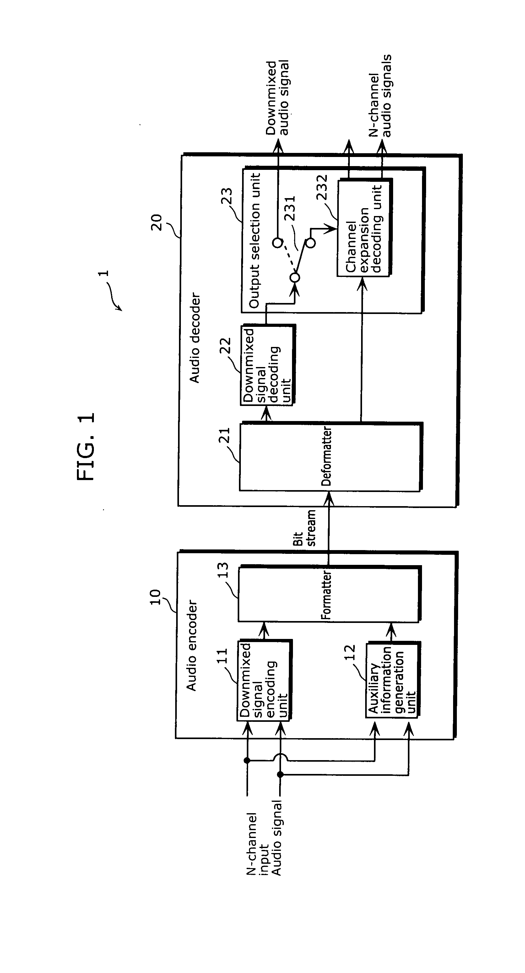
[0049]FIG. 1 is a block diagram which shows a whole configuration of the audio signal encoding / decoding system including the audio encoder of the present invention.

[0050] As shown in FIG. 1, the audio signal encoding / decoding system 1 includes an audio encoder 10 which compresses and encodes audio signals of N channels (N>1), and an audio decoder 20 which decodes the audio signals compressed and encoded by the audio encoder. Note that, for the sake of explanation, FIG. 1 shows the case of encoding two-channel audio signals.

[0051] The audio encoder 10 includes a downmixed signal encoding unit 11 which encodes a downmixed signal obtained by downmixing two-channel input audio signals, an auxiliary information generation unit 12 which generates auxiliary information (a level ratio, a phase difference) necessary for decoding the downmixed signal encoded by the downmixed signal encoding unit 11 into N-channel audio signals, and a formatter 13 which generates a bit stream by connecting, ...

second embodiment

[0087] Hereinafter, the auxiliary information generation unit according to the second embodiment of the present invention is described with reference to the drawings.

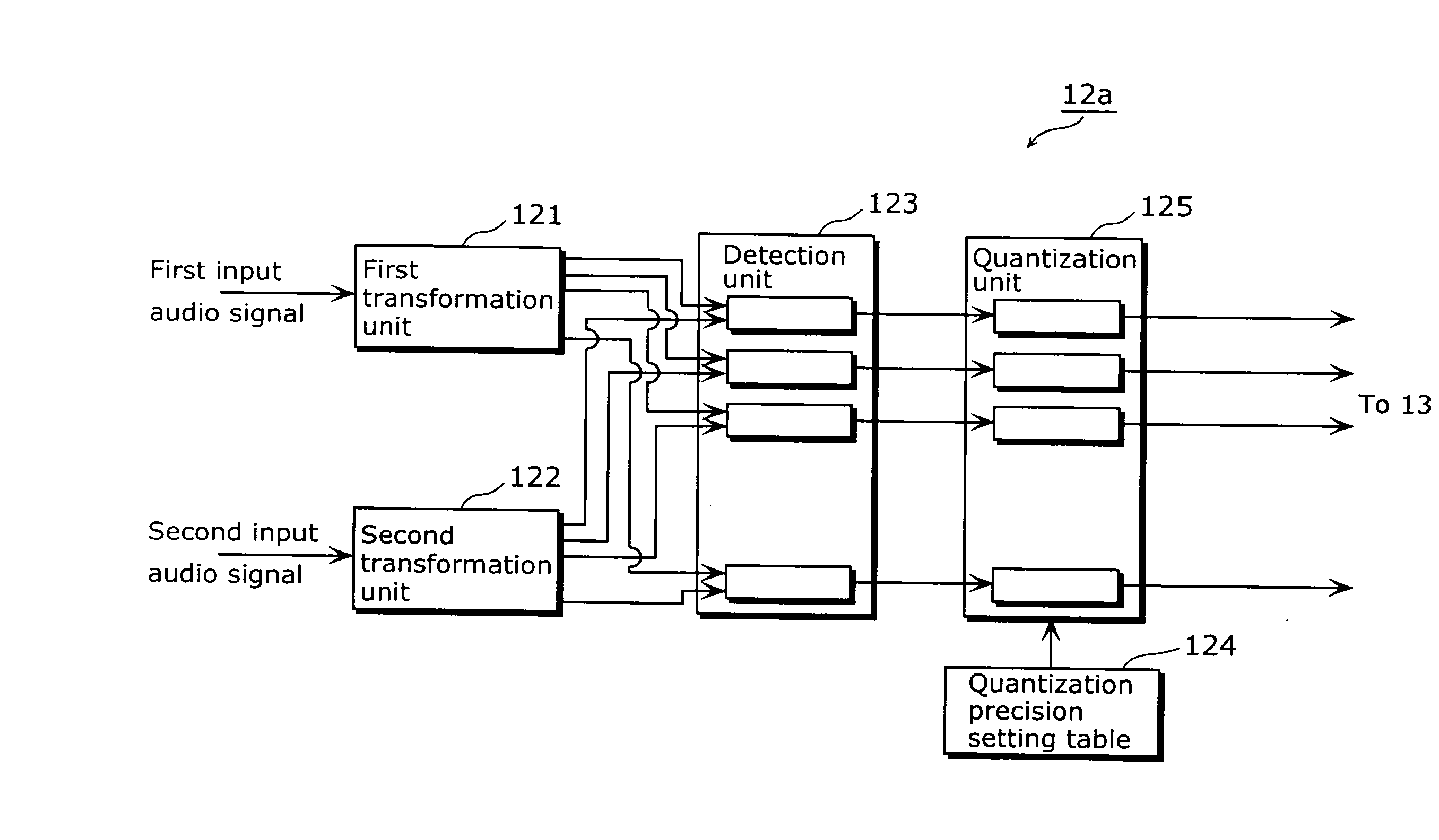
[0088]FIG. 7 is a block diagram showing an other example of a detailed structure of the auxiliary information generation unit according to the second embodiment. Here, same reference numbers are used for the constituent elements corresponding to the constituent elements of the auxiliary information generation unit 12a shown in FIG. 4, and the explanation about the same constituent elements is omitted.

[0089] As shown in FIG. 7, the auxiliary information generation unit 12b further includes a compression unit 126 in addition to the constituent elements of the auxiliary information generation unit 12 which are the first transformation unit 121, the second transformation unit 122, the detection unit 123, the quantization precision setting table 124, and the quantization unit 125.

[0090] Specifically, the second embodiment...

third embodiment

Hereinafter, the auxiliary information generation unit according to the present invention is described with reference to the drawings.

[0100]FIG. 8 is a block diagram showing an other example of a detailed structure of the auxiliary information generation unit according to the third embodiment. Here, same reference numbers are used for the constituent elements corresponding to the constituent elements of the auxiliary information generation unit 12a shown in FIG. 4, and the explanation about the same constituent elements is omitted.

[0101] As shown in FIG. 8, the auxiliary information generation unit 12c includes a first transformation unit 121, a second transformation unit 122, a first division unit 127a, a second division unit 127b, a third division unit 127c, a fourth division unit 127d, a first quantization unit 128a, and a second quantization unit 128b.

[0102] The first transformation unit 121 transforms a first input audio signal into a frequency band signal.

[0103] The second ...


PUM


Abstract

An audio encoder, which is capable of encoding multiple-channel signals so that only a downmixed signal is decoded and of further generating specific auxiliary information necessary for dividing the downmixed signal, is provided. An audio encoder (10), which compresses and encodes audio signals of N-channels (N>1), includes a downmixed signal encoding unit (11) which encodes the downmixed signal obtained by downmixing the audio signals, and an auxiliary information generation unit (12a) which generates auxiliary information necessary for decoding the downmixed signal encoded by the downmixed signal encoding unit (11) into N-channel audio signals. The auxiliary information generation unit (12a) includes transformation units (121) and (122) which transform audio signals respectively into frequency domain signals, a detection unit (123) which detects phase difference information and gain ratio information each indicates a degree of difference between frequency domain signals, and a quantization unit (125) which quantizes, for each frequency band, the phase difference information and gain ratio information detected by the detection unit (123) using the quantization precision setting table (124). The quantization precision setting table (124) functions as a division unit which divides a frequency band of a frequency domain signal into plural sub-bands.

Description

TECHNICAL FIELD [0001] The present invention relates to an audio encoder which encodes multiple-channel signals of at least two or more channels. In particular, it relates to a technique of specifically generating auxiliary information necessary for dividing a downmixed signal, which is obtained by downmixing the multi-channel signals, into original multiple-channel signals. BACKGROUND ART [0002] In recent years, the development of the technique of Spatial Codec has been encouraged. This technique aims at compressing and coding multiple-channels with a very small amount of information while maintaining a sense of realism of sounds from the multi-channels. [0003] For example, a bit rate of 512 kbps or 384 kbps is required for 5.1 channel sound by the AAC format which is a multi-channel codec that has been widely used as an audio method used for digital televisions. In contrast, Spatial Codec aims at compressing and encoding multiple-channel signals at a very small bit rate such as 12...

Claims


Application Information

Patent Timeline
Patent Type & Authority Applications(United States)
IPC IPC(8): G10L19/00G10L19/02H03M7/30G10L19/008G10L19/035
CPCG10L19/008G11B27/022G11B20/00007
Inventor MIYASAKA, SHUJITAKAGI, YOSHIAKITANAKA, NAOYATSUSHIMA, MINEO
Owner PANASONIC CORP
Features
  • R&D
  • Intellectual Property
  • Life Sciences
  • Materials
  • Tech Scout
  • Unparalleled Data Quality
  • Higher Quality Content
  • 60% Fewer Hallucinations
Learn More