Method for Forming a Cam-Engaged Rocker Arm

a technology of cam-engaged rocker arms and rocker arms, which is applied in the direction of valve arrangements, engine components, machines/engines, etc., can solve the problems of lowering strength and deficiency, and achieve the effect of accurate control

Inactive Publication Date: 2007-11-29
GENTEK TECH MARKETING
View PDF6 Cites 5 Cited by
  • Summary
  • Abstract
  • Description
  • Claims
  • Application Information

AI Technical Summary

Benefits of technology

[0006] The present invention provides a unique method for providing finished valve pad side walls and affords a substantial improvement over the known prior art because the forming of the valve guide walls are shaped after the rocker arm is formed into a U-shaped cross-section and because the quantity of material displaced to form the guide elements is accurately controllable. Material from outside the valve pad area of the U-shaped metal blank is displaced laterally by a tool which moves horizontally to transition the desired quantity of metal to create without further work the finished valve guide. Forming of the valve guide elements is effected by displacing material from the outer surface portion of the bottom of the U-shaped metal sheet and forcing it inwardly. This creates new outer surfaces which are thinner, i.e., not aligned with the central pad surface, the thickness of which remains substantially unchanged. The valve contact area surfaces are created by a tool having a width to accept a known valve stem diameter. The valve guide extensions are parallel and offset to the outer rocker arm sidewalls surfaces and by controlling displacement of the appropriate amount of metal, create guides having the proper thickness to survive in the assigned application. The height of the valve guide elements is essentially determined by the amount of material displaced horizontally inwardly by the laterally converging guide forming tool.

Problems solved by technology

In this forming operation, a deficiency may occur when the thickness of the blank area that lost material (used to create the guide) may be below required minimum thickness.
Process of this kind have the disadvantage of requiring excessive pressure and frequently yields loss of strength which results in crazing and lowering of strength as a result of the pressure needed to create a plastic flow.

Method used


Image

  • Method for Forming a Cam-Engaged Rocker Arm
  • Method for Forming a Cam-Engaged Rocker Arm
  • Method for Forming a Cam-Engaged Rocker Arm

Examples


Embodiment Construction

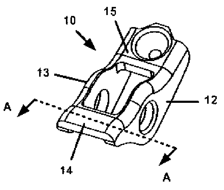
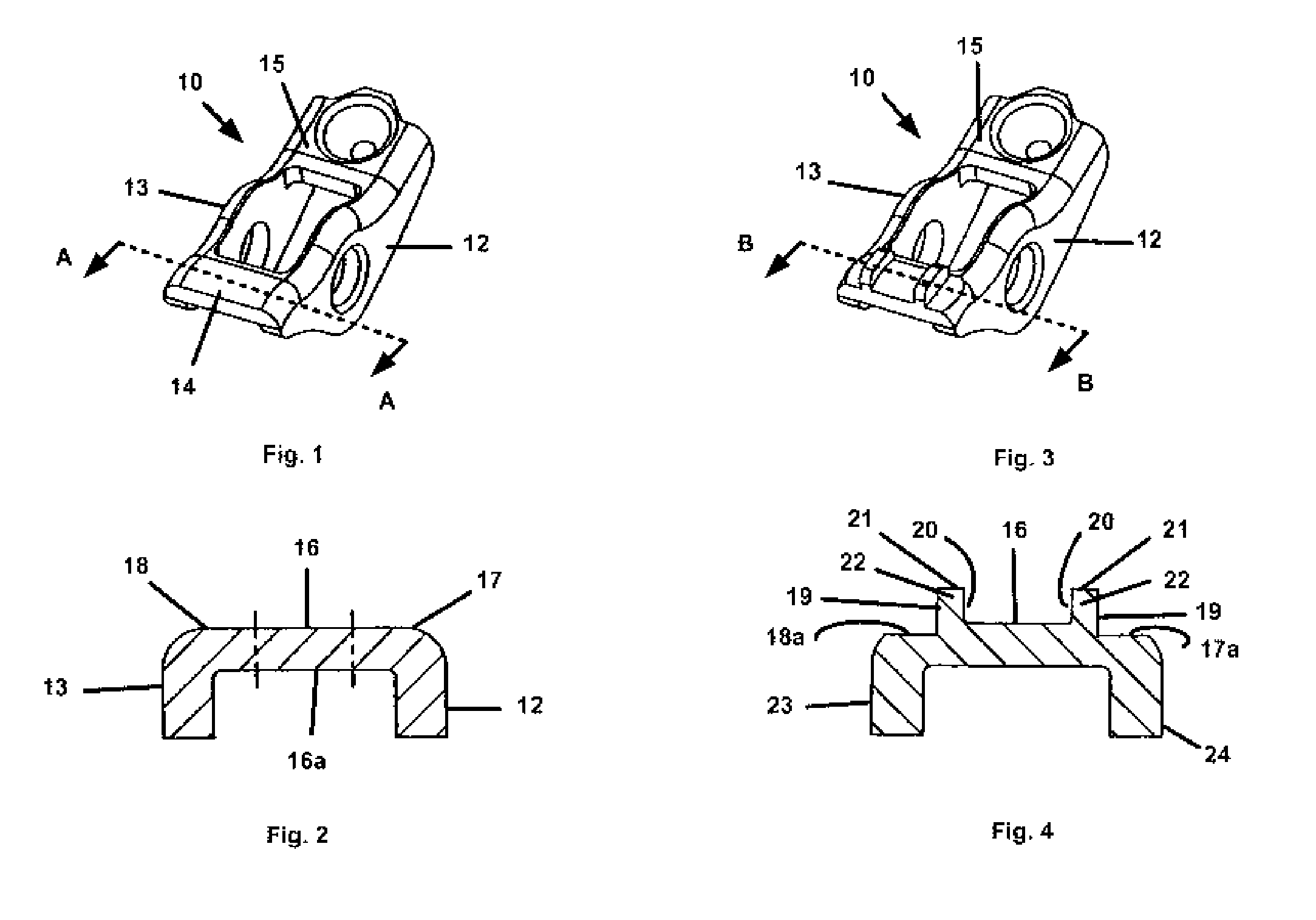
[0018] A rocker arm body 10 made by forming a steel flat blank into a U-shape cross-section comprising sidewalls 12 and 13 connected by a pad end 14 and a socket end 15. As illustrated, the pad end 14 is defined by a central section 16 and two outer surfaces 17 and 18 (FIG. 2) FIG. 4 is effected. The formation of the valve guide walls 22 by displacing material from the outer pad end surfaces 17 and 18 and forcing it inwardly or centrally towards surface 16. This creates new surfaces 17a and 18a which are not aligned with valve contact central surface 16. The valve contact area defined by surface 16 and sides 20 of the formed valve guides 22 is created by a tool having a width to accept a known valve stem diameter. The valve guide walls 22 are parallel and offset to the sidewalls 23 and 24 and are defined by outer and inner surfaces 19 and 20, respectively, and are formed so as to have a proper thickness to survive in its application. The top, i.e., height, 21 of the valve guide wall...


PUM

PropertyMeasurementUnit
depthaaaaaaaaaa
thicknessaaaaaaaaaa
diameteraaaaaaaaaa

Abstract

Valve guides are formed on a U-shaped sheet metal rocker arm by the horizontal displacement inwardly of surface metal from the outboard portion of the rocker arm. A rocker arm body made by forming a steel flat blank into a U-shape cross-section comprising sidewalls that connect a pad end and an opposite socket end. The pad end is defined by a central section and two outboard surfaces. The valve guide walls are formed by displacing material from the outboard surface portions of the pad end and forcing it centrally. This changes, i.e., diminishes, the thickness of the outboard portions of the pad end of the rocker arm which are not aligned with valve contact central surface. The valve contact area defined by horizontal surface and by the vertical sides of the formed guide extensions is created by a tool having a width to accept a known valve stem diameter. The valve guide extensions are parallel to and offset from the pad end rocker arm sidewalls and are created to have the proper thickness as well as suitable height to survive in the rocker arm application. The surface extremity, i.e., height as well as the thickness of the valve guide wall, is determined by the amount of material displaced from surfaces of the outboard portion of the pad end of the rocker arm. Valve guide extension height and thickness dimensions can be achieved that were not attainable by known prior art methods.

Description

[0001] This application is a continuation-in-part application of application Ser. No. 10 / 927,372, filed on Aug. 20, 2004, and claims the benefit of Provisional Application No. 60 / 498,076, filed on Aug. 27, 2003, the contents of which are hereby incorporated herein in their entirety.TECHNICAL FIELD [0002] The present invention relates to a method of forming a rocker arm by stamping metal blanks. More particularly, the invention relates to a novel method of forming finished valve guides for the rocker arm by the horizontal displacement inwardly of metal from the outer sides at the bottom of the bent U-shaped rocker arm at the pad end of the rocker arm. BACKGROUND OF THE INVENTION [0003] In automotive and other applications, an overhead cam engine typically utilizes a plurality of cam engaged rocker arms which function to open valves. These rocker arms pivot at one end, contact the valve at an opposite end, and support a roller between the two ends. The roller engages the cam and the c...

Claims


Application Information

Patent Timeline
Patent Type & Authority Applications(United States)
IPC IPC(8): B21D31/00
CPCB21K1/205F01L1/185
Inventor SMITH, SCOTTMILLS, DAN
Owner GENTEK TECH MARKETING
Why Eureka
Try Eureka