Ventilator circuit for oxygen generating system

a technology of oxygen generating system and ventilator, which is applied in the field of ventilator circuit, can solve the problems of insufficient capacity of respiratory and/or circulatory system of many patients to sustain patients, inability to have high pressure oxygen available in sufficient volume, and inability to meet the needs of patients,

Active Publication Date: 2007-11-29
ZOLL MEDICAL CORPORATION
View PDF8 Cites 41 Cited by
  • Summary
  • Abstract
  • Description
  • Claims
  • Application Information

AI Technical Summary

Benefits of technology

[0011]The ventilator circuit includes or communicates with a low pressure low flow source of oxygen. More particularly, an oxygen fill line extends from the low pressure low flow oxygen source and communicates with the inspiratory line at a location between the oxygen fill enable valve and the exhalation valve, and preferably at a location close to the exhalation valve. A one way check valve is incorporated into the inspiratory line between the oxygen fill line and the exhalation valve. The check valve permits the low pressure low flow oxygen to fill the inspiratory line without venting through the exhalation valve during exhalation cycles. The check valve also seals off a leak path that might otherwise exist through the oxygen fill enable valve during the exhalation cycle. As a result, exhaled air containing carbon dioxide does not flow into the inspiratory line during the exhalation cycle. Rather, oxygen from the low pressure low flow oxygen source is permitted to flow through the oxygen fill line and into the inspiratory line during exhalation cycles. A second check valve permits directional gas flow from the low pressure low flow oxygen source to pass through the oxygen fill line into the inspiratory line and prevents gas from flowing from the inspiratory line into the oxygen fill line, particularly if a low pressure low flow oxygen source is not connected.
[0012]The disposition of the oxygen fill enable valve and the exhalation valve change during the inspiration cycle so that the air oxygen mix can flow to the patient connection. However, the initial flow of gas to the patient at the start of the inspiratory cycle is the gas that resides in the inspiratory line at the end of the expiration cycle. Unlike the prior art system described above, the subject ventilator circuit ensures that the initial flow of gas to the patient during the inspiratory cycle is sufficiently rich in oxygen due to the flow of oxygen from the low pressure low flow oxygen source through the oxygen fill line and into the inspiratory line during the exhalation cycle. As a result, the patient is assured of achieving an air oxygen mix that is appropriately rich in oxygen during the first two thirds of the inspiratory cycle where it matters the most.

Problems solved by technology

The respiratory and / or circulatory systems of many patients may not be sufficiently viable to sustain the patient with oxygen levels that exist in ambient air.
The ability to have high pressure oxygen available in sufficient volume is not always possible or practical.
Hospitals maintain a limited supply of oxygen that is stored in cylinders for intra-hospital transport and backup use in the event that the primary system fails.
The cylinder size can impose handling constraints on the caregiver and mobility constraints on the patient.
Reliance on oxygen cylinders also can present a risk if resupply is not available.
The typical prior art ventilator circuit, by design, is incompatible for direct use with oxygen enrichment devices.
This can quickly deplete a limited supply of oxygen.

Method used


Image

  • Ventilator circuit for oxygen generating system
  • Ventilator circuit for oxygen generating system
  • Ventilator circuit for oxygen generating system

Examples


first embodiment

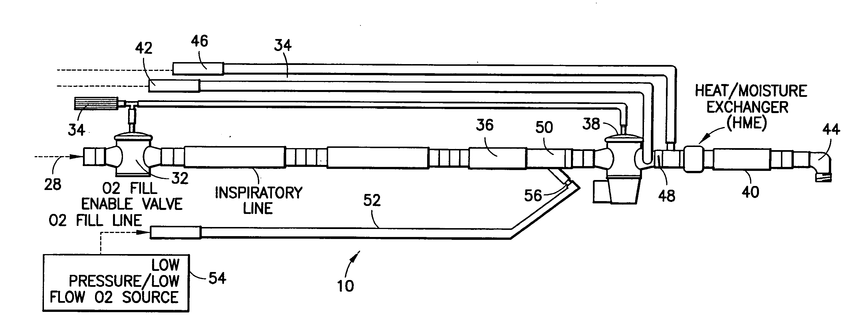
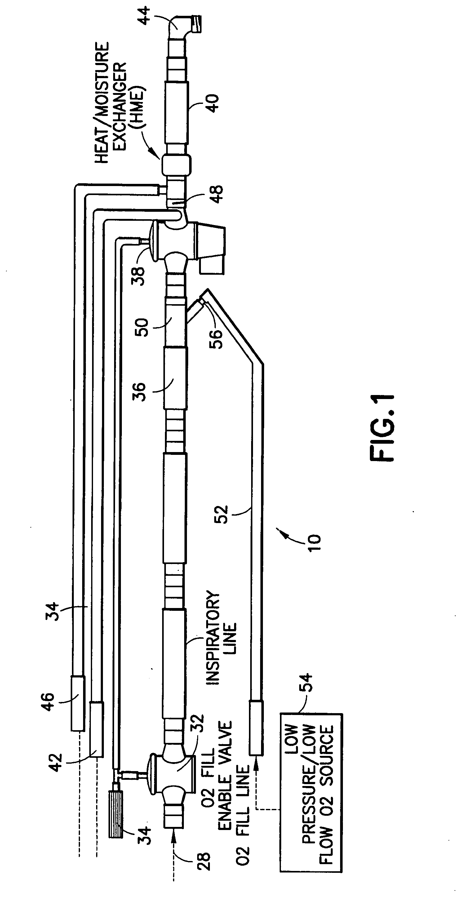
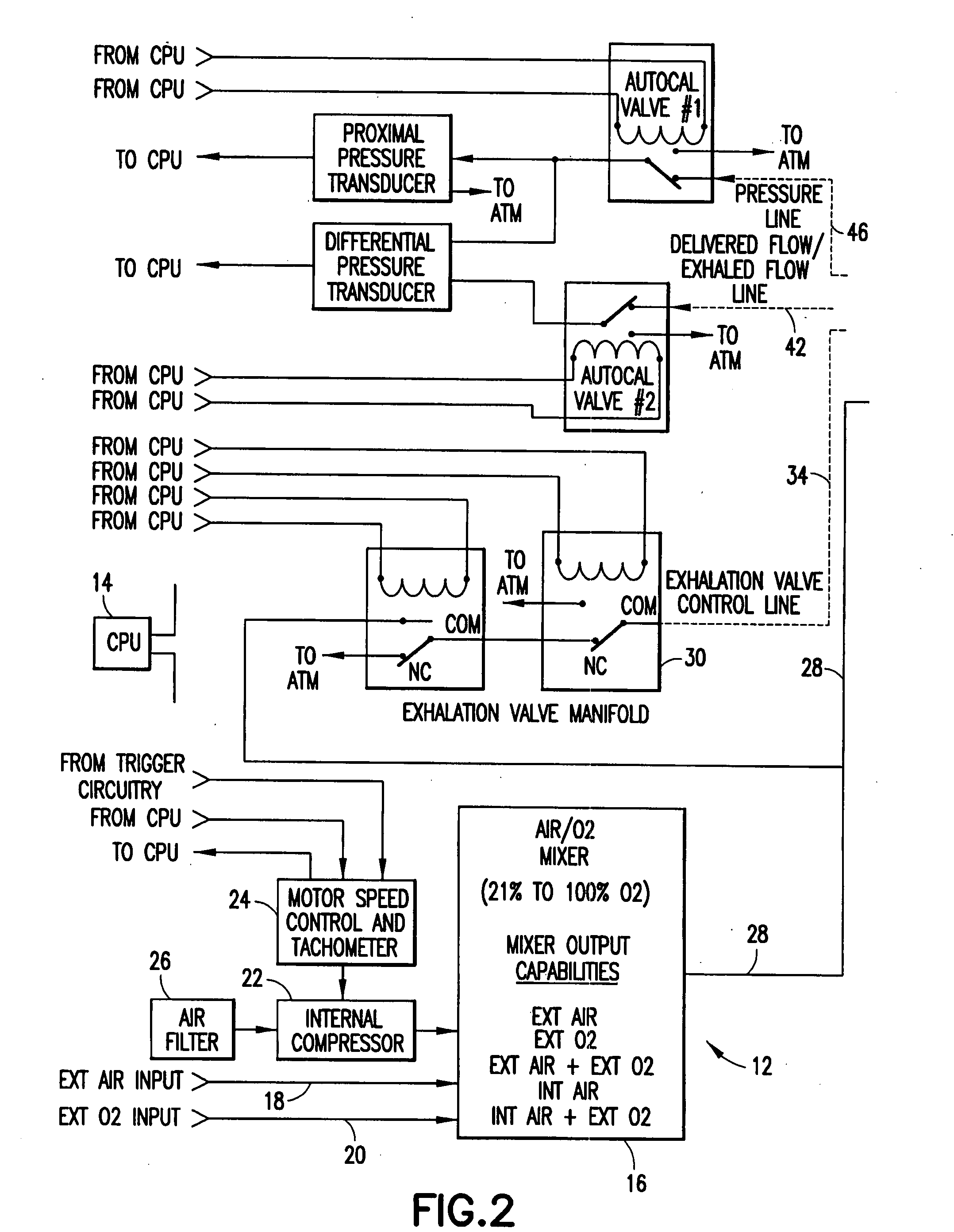
[0021]a ventilator circuit in accordance with the subject invention is identified generally by the numeral 10 in FIG. 1. The ventilator circuit 10 is used with a ventilator 12 as shown in FIG. 2. More particularly, the ventilator 12 of FIG. 2 includes a CPU 14 that controls the operation of the ventilator 12 and its ventilator circuit 10. The ventilator 12 is operative to deliver an air / O2 mixture to the ventilator circuit 10. More particularly, an air / O2 mixer 16 is incorporated into the ventilator 12 and may be controlled by signals generated by the CPU 14. The air / O2 mixer 16 includes an external air input 18 and an external O2 input 20 that communicate respectively with supplies of external air and oxygen. The CPU settings determine the proportion of air and oxygen to create the desired mixture. The air input to the air / O2 mixer 16 can be driven by an internal compressor 22 rather than an external air supply. In this case, a motor speed control and tachometer 24 communicates wit...

third embodiment

[0030]FIGS. 4 and 5 show the ventilator circuit. The ventilator circuit of FIG. 4 is a dual limb circuit and is identified generally by the numeral 300 in FIG. 3. The FIG. 4 embodiment is structurally and functionally very similar to the FIG. 2 embodiment. In particular, a wye fitting 60 is in substantially the same position depicted in the FIG. 2 embodiment. However, the FIG. 4 ventilator circuit 300 further includes an expiratory line 62 that extends from wye fitting 60 to the exhalation valve 38. This embodiment further has the O2 fill enable valve 32 and the exhalation valve 38 as being parts of the ventilator 12, as shown in FIG. 5. However, the ventilator circuit 10 and the ventilator 12 cooperate to function substantially the same as in the first two embodiments.

[0031]FIG. 6 shows a further variation of the ventilator circuit, and specifically depicts a dual lumen circuit identified generally by the numeral 400. In particular, the ventilator circuit 400 of FIG. 6 has a dual l...


PUM


Abstract

A ventilator circuit is provided for use with a ventilator and a low pressure low flow oxygen source to provide a hyper-oxygenated mixture of air and oxygen at the onset of inspiration. The ventilator circuit achieves this result by using its inspiratory limb to store oxygen between breaths. As a result, the oxygen content of dead space gas is increased before delivery to the distal alveoli of the patient. Accordingly, the ventilator circuit achieves an efficient use of available oxygen and requires less oxygen to a desired oxyhemoglobin percentage at the patient.

Description

[0001]This application claims priority on U.S. Provisional Patent Appl. No. 60 / 800,913, filed May 16, 2006.BACKGROUND OF THE INVENTION[0002]1. Field of the Invention[0003]The invention relates to a ventilator circuit for use with a low pressure low flow oxygen generator that by design requires less oxygen to achieve a desired oxyhemoglobin percentage at the patient as compared to conventional means of oxygen delivery.[0004]2. Description of the Related Art[0005]The respiratory and / or circulatory systems of many patients may not be sufficiently viable to sustain the patient with oxygen levels that exist in ambient air. A typical ventilator system contains a means to deliver ambient or compressed air to a patient. The ventilator typically has means to accept oxygen from a high pressure or low pressure source and to vary the mixture of air and oxygen. A ventilator circuit communicates with the ventilator and the patient. The ventilator circuit provides a conduit for the gas or gas mixt...

Claims


Application Information

Patent Timeline
Patent Type & Authority Applications(United States)
IPC IPC(8): A61M16/00A62B7/00
CPCA61M16/08A61M16/1045A61M16/12A61M16/208A61M2016/0027A61M16/201A61M2202/0208A61M2205/3365A61M16/0063A61M16/0858A61M2016/0036A61M16/0816A61M16/0833A61M16/107
Inventor SHERMAN, LESLIE H.BECK, GEORGE
Owner ZOLL MEDICAL CORPORATION
Why Eureka
Try Eureka