Optical mark reader

a technology of optical marks and readers, applied in the field of automatic scoring, can solve the problems of high production costs of such forms, scanners that do not produce electronic image reproduction, and inadvertently make stray marks near targets

Inactive Publication Date: 2007-11-29
SCAN-OPTICS
View PDF6 Cites 14 Cited by
  • Summary
  • Abstract
  • Description
  • Claims
  • Application Information

AI Technical Summary

Benefits of technology

[0012]It is an object of the present invention to provide a digital form scoring system that ...

Problems solved by technology

In other cases, a stray mark may inadvertently be made near a target.
This is in addition to deviations that arise from imperfect printing of the form, and misalignment or bending of the form as it passes through the scoring system.
These scanners do not work by producing an electronic image reproduction of the contents of the forms; they merely sense the darkness levels of certain predefined fixed locations of the forms.
Production of such forms is very expensive and is usually available only from a single source, namely, the same company that produces the LED scanner.
Although forms spe...

Method used


Image

  • Optical mark reader
  • Optical mark reader
  • Optical mark reader

Examples


Embodiment Construction

I. System Overview

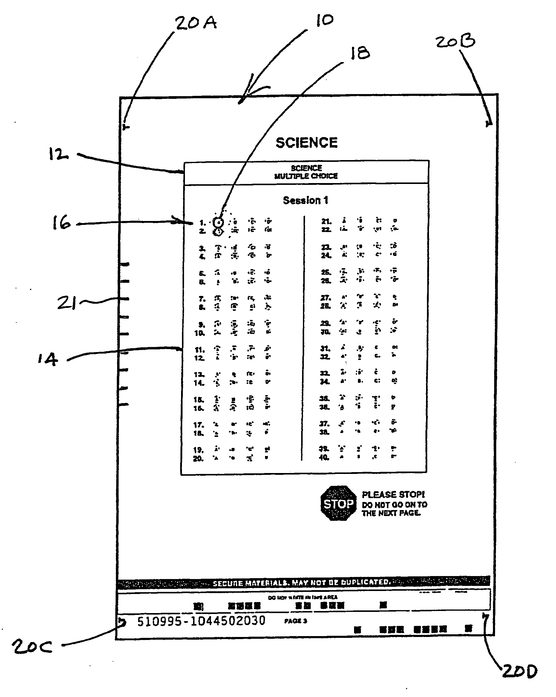
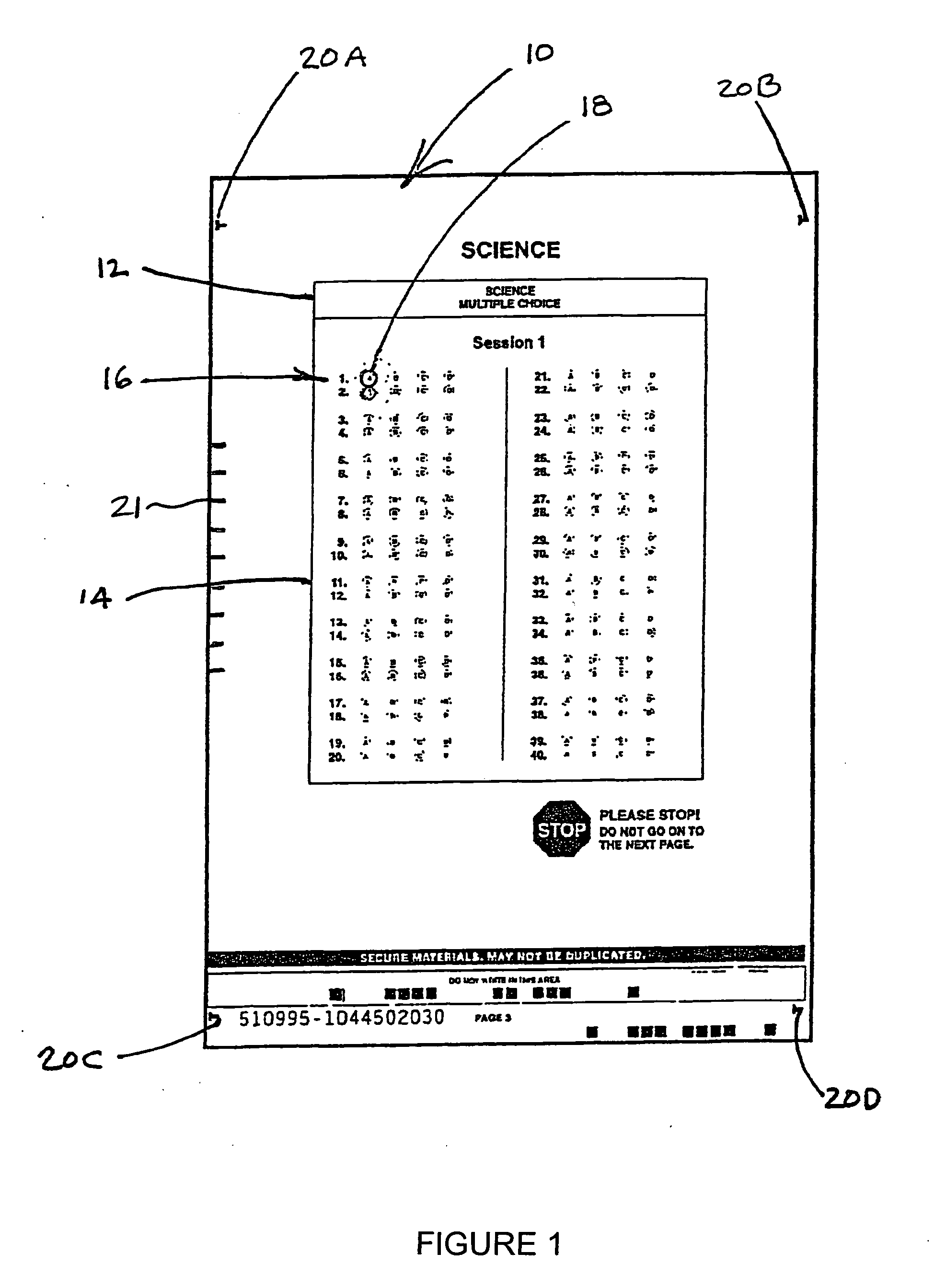
[0035]The system and method according to the incorporated disclosure and present disclosure can be implemented in a variety of contexts, with only the preferred embodiment described in the present specification. This preferred embodiment is in the context of a multi-page student examination booklet with associated bubble targets, which the students mark with an ordinary lead pencil to indicate the selected responses to the examination questions. It should be understood that the terminology, labels, and screen displays described in the present application are for illustrative purposes only and that the claims, not the preferred embodiment as described, define the scope of patent rights.

[0036]FIG. 1 is a representation of a one page, preprinted master form 10 which may contain a plurality of sections such as 12, 14. Section 14 has a multiplicity of target groups, one of which is shown at 16, consisting of a plurality of targets 18. In this example, the target group 1...


PUM


Abstract

A digital form scoring system that does not require that the targets on the marked form be digitally captured with a drop-out scanner. This is accomplished by locating each target, and in the mark interpretation logic, sensing an area within the outline of the target, then digitally removing all or most of thin lines of print that form a symbol or character within the outline, and removing the shading in the background, before applying the logic that determines whether a region of dark gray scale values in the sensing area should be considered a valid mark entered by the subject.

Description

BACKGROUND OF THE INVENTION[0001]The present invention relates to the automated scoring of so-called “bubble” forms or the like, whereby each of a multiplicity of end users such as students, voters, and questionnaire respondents, enters marks on a standard form associated with the individual, to indicate the specific choices from among those offered on the form. The marks are typically entered by darkening (filling in) preprinted circles or ellipses with a pencil. Inevitably, some of the respondents apply very light pressure on the pencil and therefore produce a very light mark. The marks made by other respondents may either extend out of the designated target, or partially within and partially outside of the target. In other cases, a stray mark may inadvertently be made near a target. These deviations give rise to the need for interpretation of the intent of the user. This is in addition to deviations that arise from imperfect printing of the form, and misalignment or bending of th...

Claims


Application Information

Patent Timeline
IPC IPC(8): G06K7/10G06V30/10
CPCG06K9/346G09B7/02G09B3/04G06K17/0032G06V30/10G06V30/155
Inventor SCANLON, EDWARD F.
Owner SCAN-OPTICS
Why Eureka
Try Eureka